
Method and apparatus for controlling oil well drill site systems

a technology for oil wells and control systems, applied in the direction of instruments, detection using electromagnetic waves, borehole/well accessories, etc., can solve the problems of wiring, switches, other connections, special challenges for connecting and protecting control electronics, and are subject to extremely harsh and often corrosive conditions, so as to avoid damage to wiring and other components.

Inactive Publication Date: 2017-09-19
HICKMAN DON DARRELL
View PDF7 Cites 8 Cited by
  • Summary
  • Abstract
  • Description
  • Claims
  • Application Information

AI Technical Summary

Benefits of technology

The system improves safety and efficiency by automating operations, reducing component damage, and allowing for real-time data analysis and remote control, enhancing reliability and reducing personnel requirements at the well site.

Problems solved by technology

The harsh conditions and hazards present special challenges for connecting and protecting control electronics.
Wiring, switches and other connections are subject to extremely harsh and often corrosive conditions and are subject to a higher failure rate.
Moreover, control equipment is also subject to harsh operating conditions and also has a higher incidence of problems.
In addition, the information gathered relating to various parameters of drilling and connecting elements such as tubing or sucker rods has been limited for prior art systems.
Even if such information exists, accessing and analyzing the information for modifying operations have also been limited.

Method used


Image

  • Method and apparatus for controlling oil well drill site systems
  • Method and apparatus for controlling oil well drill site systems
  • Method and apparatus for controlling oil well drill site systems

Examples


Embodiment Construction

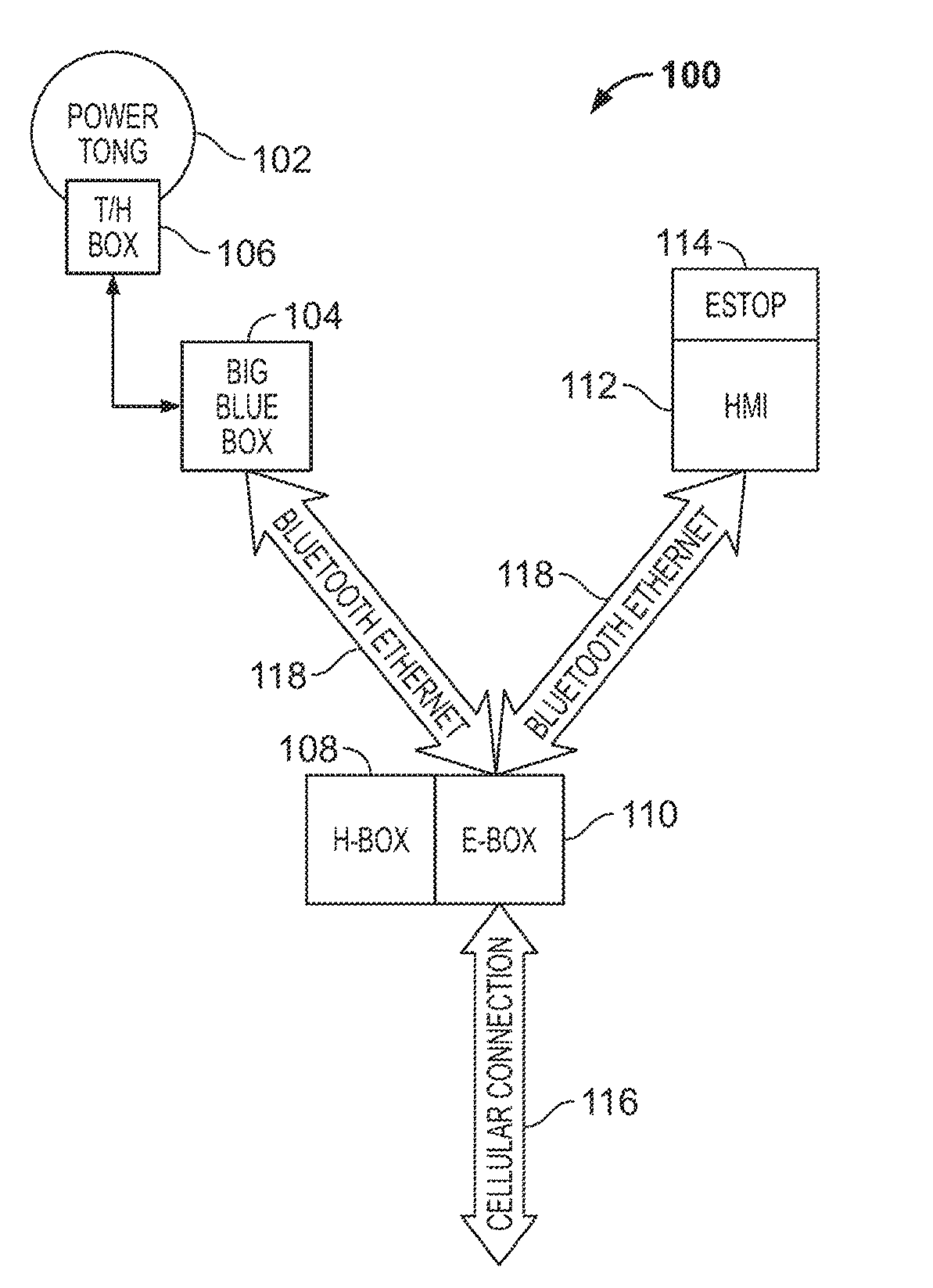
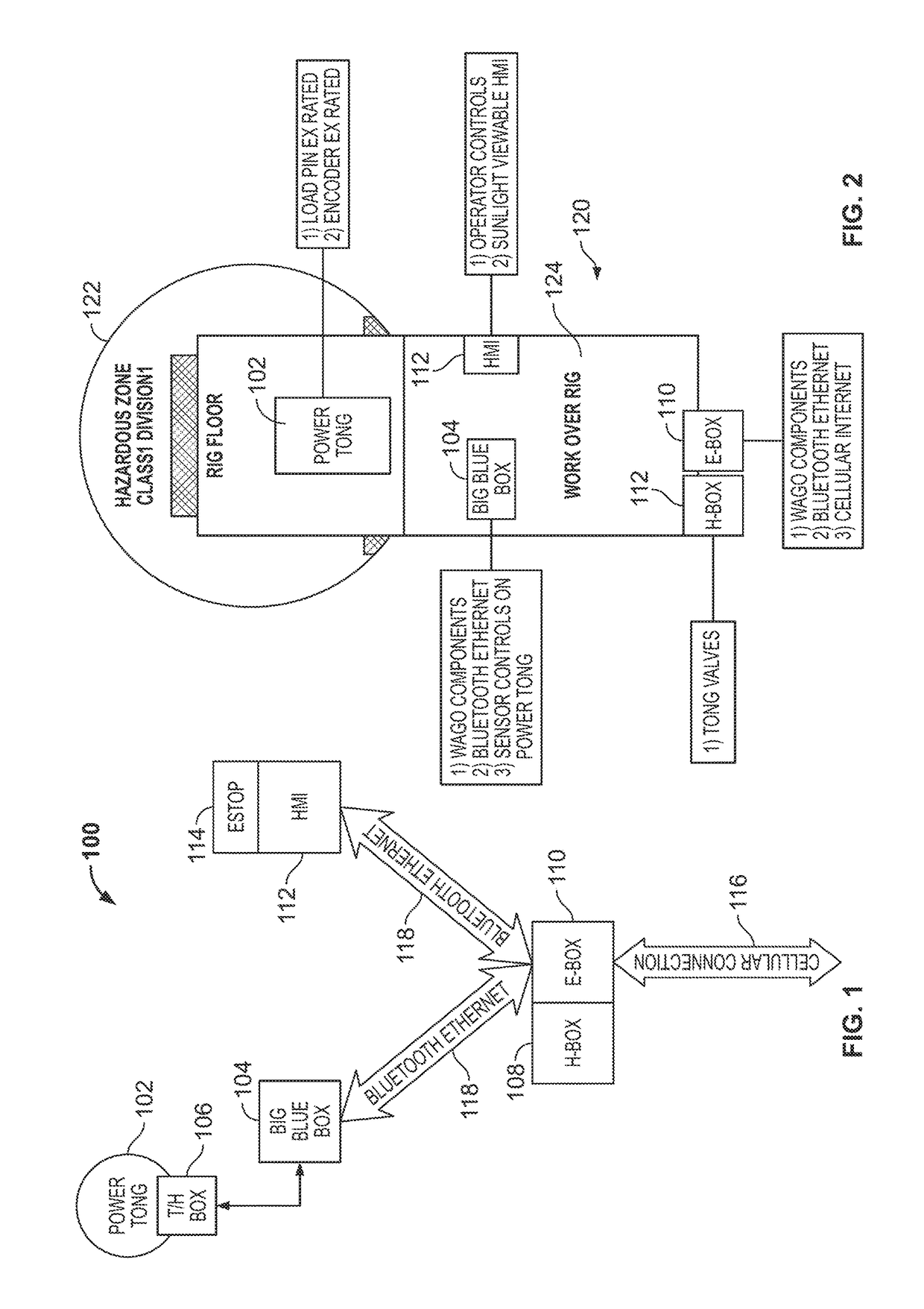
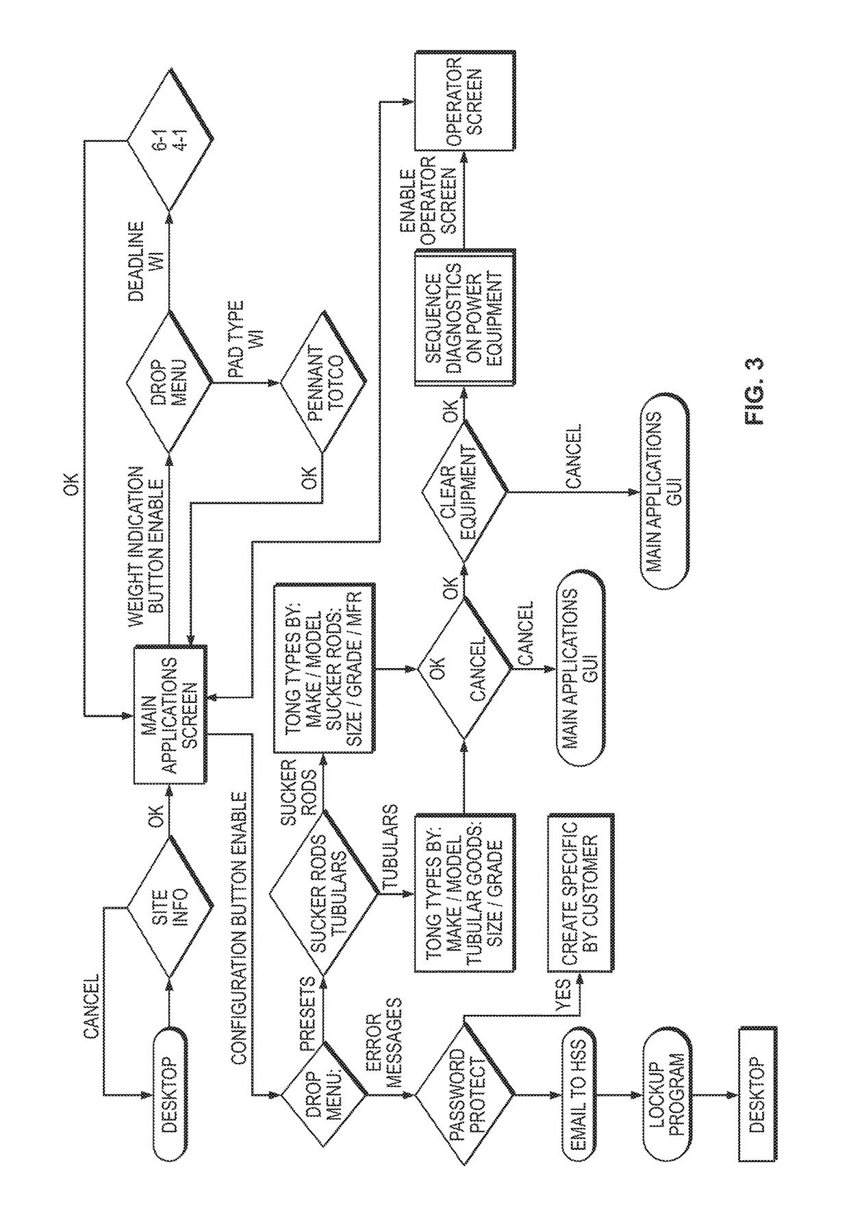
[0030]Referring now to the drawings and in particular to FIGS. 1 and 2, there is shown a control system 100 for acquiring and analyzing data to control equipment at a well site. The control system 100 includes multiple protected subsystems or modules. A tong hydraulics module 106 within the hazardous explosion zone 122 is protected in an explosion rated box 106A. Other components are located remotely from the hazardous explosion zone 122. The other control components are placed in enclosures to protect them from the elements and communicate via Bluetooth or other wireless communication. Therefore, problems associated with corrosion or other damage to wiring, relays and switches are eliminated. Moreover, the various components provide for automatic control of the tong 102 and automatic recording of operational data. The information is forwarded to a human machine interface 112 with a processor and may also be transmitted to remove locations for real time monitoring and automation of ...


PUM


Abstract

A control system for a well site, the well site includes connectable elements configured for inserting down a well. An explosion hazard zone surrounds the well site. A first electronics enclosure is remote from the explosion hazard zone and houses a first electronics module. A remote electronics control module is spaced apart from the first electronics housing and a remote hydraulics module removed from the first electronics module and the hazard zone module. The control system includes a human machine interface including a display and input. A central communications module is in wireless communication with the first electronics control module, the remote electronics module, and a remote location. A processor is in one or more of the first electronics module, the communications module or the human machine interface.

Description

BACKGROUND OF THE INVENTION[0001]Field of the Invention[0002]The present invention relates to a control system and control method for an oil well site and in particular to a system for providing automation and automatic wireless control of operations at a well site.[0003]Description of the Prior Art[0004]Management of elements used for drilling and pumping oil from well sites has historically been largely performed manually. The harsh conditions and hazards present special challenges for connecting and protecting control electronics. Moreover, areas around the well head require certain explosion proof rated components in many uses. Wiring, switches and other connections are subject to extremely harsh and often corrosive conditions and are subject to a higher failure rate. Moreover, control equipment is also subject to harsh operating conditions and also has a higher incidence of problems.[0005]In addition, the information gathered relating to various parameters of drilling and conne...

Claims


Application Information

Patent Timeline
Patent Type & Authority Patents(United States)
IPC IPC(8): G01V3/00E21B33/035G01V3/30E21B44/00
CPCG01V3/30E21B33/0355E21B44/00
Inventor HICKMAN, DON DARRELL
Owner HICKMAN DON DARRELL
Learn More