Fuel injection control device and fuel injection system

a control device and fuel injection technology, applied in the direction of fuel injecting pumps, electric control, machines/engines, etc., can solve the problems of fuel having a small spray particle diameter, fuel cannot be injected, and the supply fuel pressure needs to be decreased, so as to prevent the energy required for the drive of the high-pressure pump from becoming unnecessarily large, the spray particle diameter is small, and the effect of reducing the energy consumption

Active Publication Date: 2017-09-19
DENSO CORP
View PDF20 Cites 4 Cited by
  • Summary
  • Abstract
  • Description
  • Claims
  • Application Information

AI Technical Summary

Benefits of technology

[0018]Contrary to the present disclosure, if the target pressure is set in accordance with the operating condition of the engine also at the time of partial injection, the target pressure becomes small due to the small required injection quantity so that fuel may not be injected with a small spray particle diameter. On the other hand, in the present disclosure, at the time of partial injection, the target pressure is set at a value that is a preset lower limit pressure or higher. Accordingly, at the time of partial injection, fuel is injected at a sufficiently high supply fuel pressure, so that a small spray particle diameter can be obtained even by the partial injection. Therefore, a minutely small amount of fuel can be injected with the spray particle diameter made small. Furthermore, at the time of full lift injection, the target pressure is set according to the operating condition of the engine. As a consequence, at the time of full lift injection, unnecessarily high supply fuel pressure can be avoided, and the energy required for the drive of the high-pressure pump can be prevented from becoming unnecessarily large.

Problems solved by technology

However, at the time of the above-described full lift injection, in the case of injection of a minutely small amount of fuel, the supply fuel pressure needs to be decreased.
Thus, atomization of the fuel spray cannot be sufficiently promoted to cause deterioration of combustion efficiency.
Thus, fuel having a small spray particle diameter cannot be injected.

Method used


Image

  • Fuel injection control device and fuel injection system
  • Fuel injection control device and fuel injection system
  • Fuel injection control device and fuel injection system

Examples


first embodiment

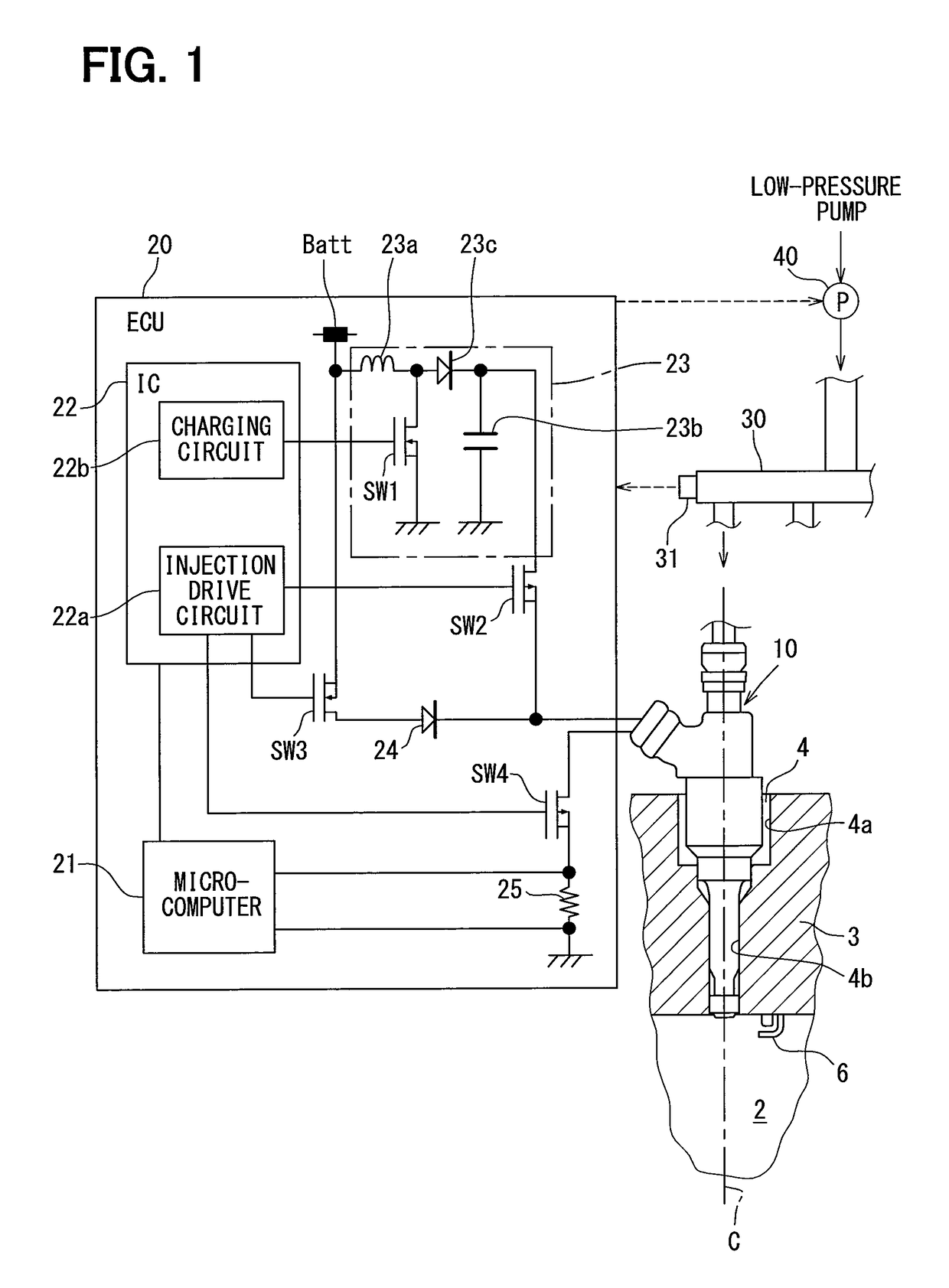
[0034]An injector 10 illustrated in FIG. 1 is disposed in an ignition-type internal combustion engine (gasoline engine) to inject fuel directly into a combustion chamber 2 of the engine. Specifically, an attachment hole 4, into which the injector 10 is inserted, is formed at a position of a cylinder head 3 defining the combustion chamber 2 that accords with an axis C of a cylinder.

[0035]The fuel supplied to the injector 10 is stored in a fuel tank (not shown). The fuel in the fuel tank is pumped up by a low-pressure pump, and is pressure-fed into a delivery pipe 30 with its pressure raised by a high-pressure pump 40. The high-pressure fuel in the delivery pipe 30 is distributed and supplied to an injector 10 of each cylinder. Structure of the high-pressure pump 40 will be described later in detail in reference to FIG. 5.

[0036]An ignition plug 6 is attached to the cylinder head 3. The ignition plug 6 and the injector 10 are arranged side by side at parts of the cylinder head 3 that a...

second embodiment

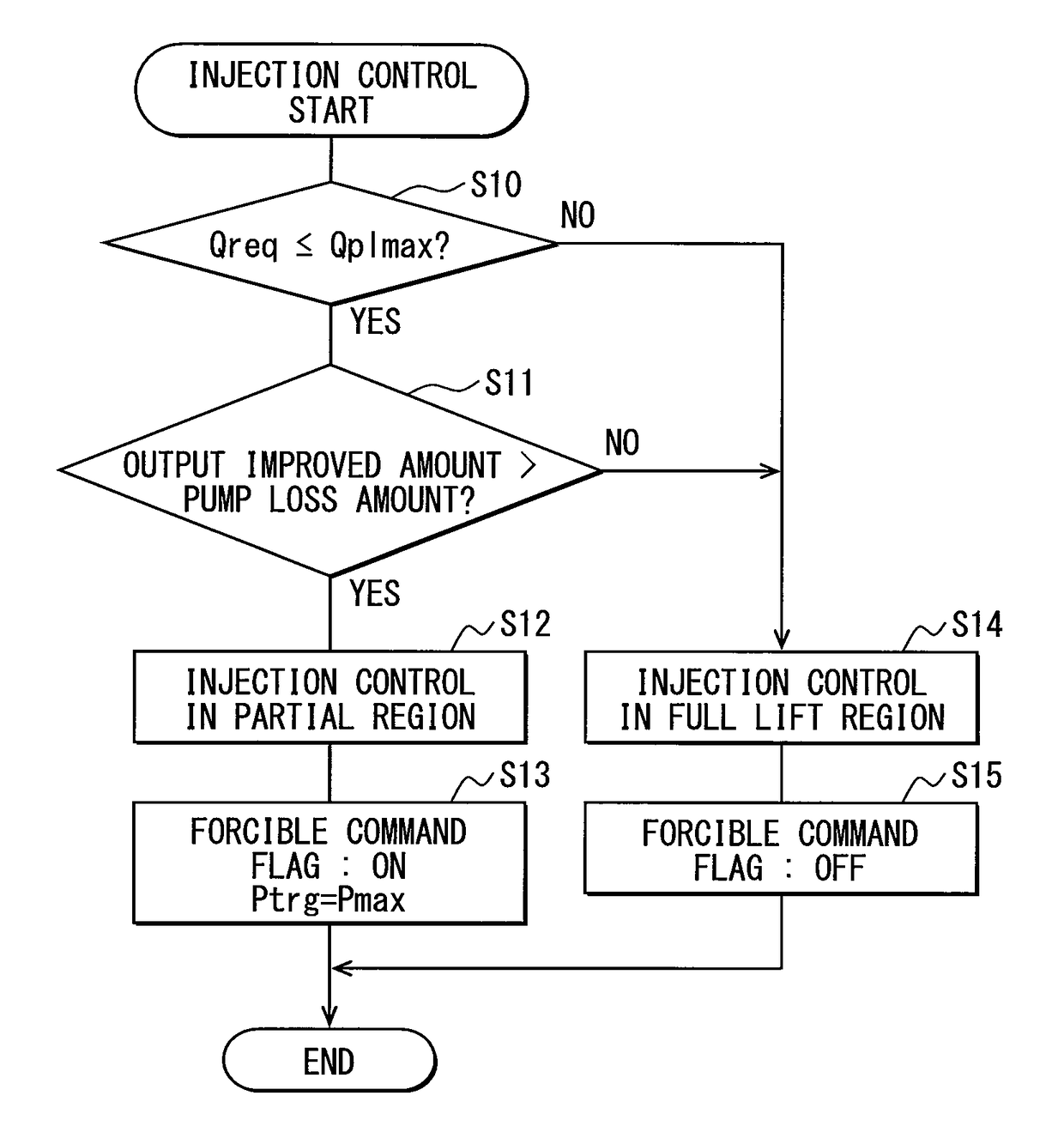
[0119]In the above first embodiment, at S11 in FIG. 8, the output improved amount and the pump loss amount are calculated, and it is determined whether the inequation: output improved amount>pump loss amount is satisfied based on this calculation result. In the present embodiment, at the time of starting of the engine, the output improved amount and the pump loss amount are not calculated, and the full lift injection is chosen with the output improved amount considered to be smaller than the pump loss amount.

[0120]The “time of starting” in this case means the time while the engine is driven by a starter motor. At such starting time, it is highly probable that the output improved amount is larger than the pump loss amount. Accordingly, in the present embodiment, a processing load of a microcomputer 21 which calculates the output improved amount and the pump loss amount is reduced, and the control which performs the full lift injection in the case of output improved amount

third embodiment

[0121]In the above first embodiment, at S10 in FIG. 8, a small-large comparison is made between the partial maximum injection quantity Qplmax and the required injection quantity Qreq, and based on this comparison result, it is determined whether the partial injection is carried out. In the present embodiment, when the engine is in idle operation, the small-large comparison between Qplmax and Qreq is not made, and the partial injection is chosen with the required injection quantity Qreq considered to be equal to or smaller than the partial maximum injection quantity Qplmax.

[0122]At such time of idle operation, it is highly probable that the required injection quantity Qreq is equal to or smaller than the partial maximum injection quantity Qplmax. For this reason, in the present embodiment, a processing load of a microcomputer 21 which makes the small-large comparison between Qplmax and Qreq can be reduced, and control can be performed to carry out the partial injection in the case of...


PUM


Abstract

A fuel injection control device is adapted for a fuel injection system including an injector and a high-pressure pump that raises pressure of fuel and supplies the fuel to the injector. The fuel injection control device includes a selecting unit for selecting by which one of full lift injection and partial injection to inject fuel, and a pump control unit for controlling operation of the high-pressure pump such that a pressure of fuel supplied to the injector coincides with a target pressure. The selecting unit selects the partial injection when a required injection quantity of fuel is equal to or smaller than a partial maximum injection quantity. A fuel injection system includes the fuel injection control device, the injector, and the high-pressure pump.

Description

CROSS REFERENCE TO RELATED APPLICATIONS[0001]This application is the U.S. national phase of International Application No. PCT / JP2014 / 002457 filed 9 May 2014, which designated the U.S. and claims priority to Japanese Patent Application No. 2013-100302 filed on May 10, 2013 and Japanese Patent Application No. 2013-100300 filed on May 10, 2013, the disclosures of each of which are hereby incorporated herein by reference.TECHNICAL FIELD[0002]The present disclosure relates to a fuel injection control device applied to a fuel injection system that injects fuel, whose pressure has been raised by a high-pressure pump, through a injector, and a fuel injection system.BACKGROUND ART[0003]This kind of a common injector includes a fixed core that generates electromagnetic attractive force upon energization of a coil, and a movable core that is attracted to the fixed core and is displaced together with a valving element. Through control of an energization time Ti for the coil, a valve-open time o...

Claims


Application Information

Patent Timeline
Patent Type & Authority Patents(United States)
IPC IPC(8): F02D41/24F02M51/06F02M63/00F02M61/04F02M59/20F02M61/18F02D41/40F02D41/30F02D41/20F02D41/38F02M59/10
CPCF02D41/3005F02D41/20F02D41/247F02D41/3082F02D41/3845F02D41/40F02D41/401F02M51/0671F02M51/0685F02M59/20F02M61/04F02M61/18F02M61/1846F02M61/1853F02M63/0019F02M63/0021F02D2041/2055F02D2200/0602F02D2200/0616F02D2250/31F02M59/102F02M2200/08Y02T10/44Y02T10/40
Inventor IMAI, KEITANAGATOMO, HIROAKIITOH, EIJI
Owner DENSO CORP
Why Eureka
Try Eureka