
Foldable headrest with double hinge

a headrest and hinge technology, applied in the field of headrests, can solve the problems of limited overall mechanism of the turn-down device, and achieve the effect of improving the construction size of the vehicle seat and the widest possible swivel angle rang

Active Publication Date: 2017-09-19
FORD GLOBAL TECH LLC
View PDF27 Cites 0 Cited by
  • Summary
  • Abstract
  • Description
  • Claims
  • Application Information

AI Technical Summary

Benefits of technology

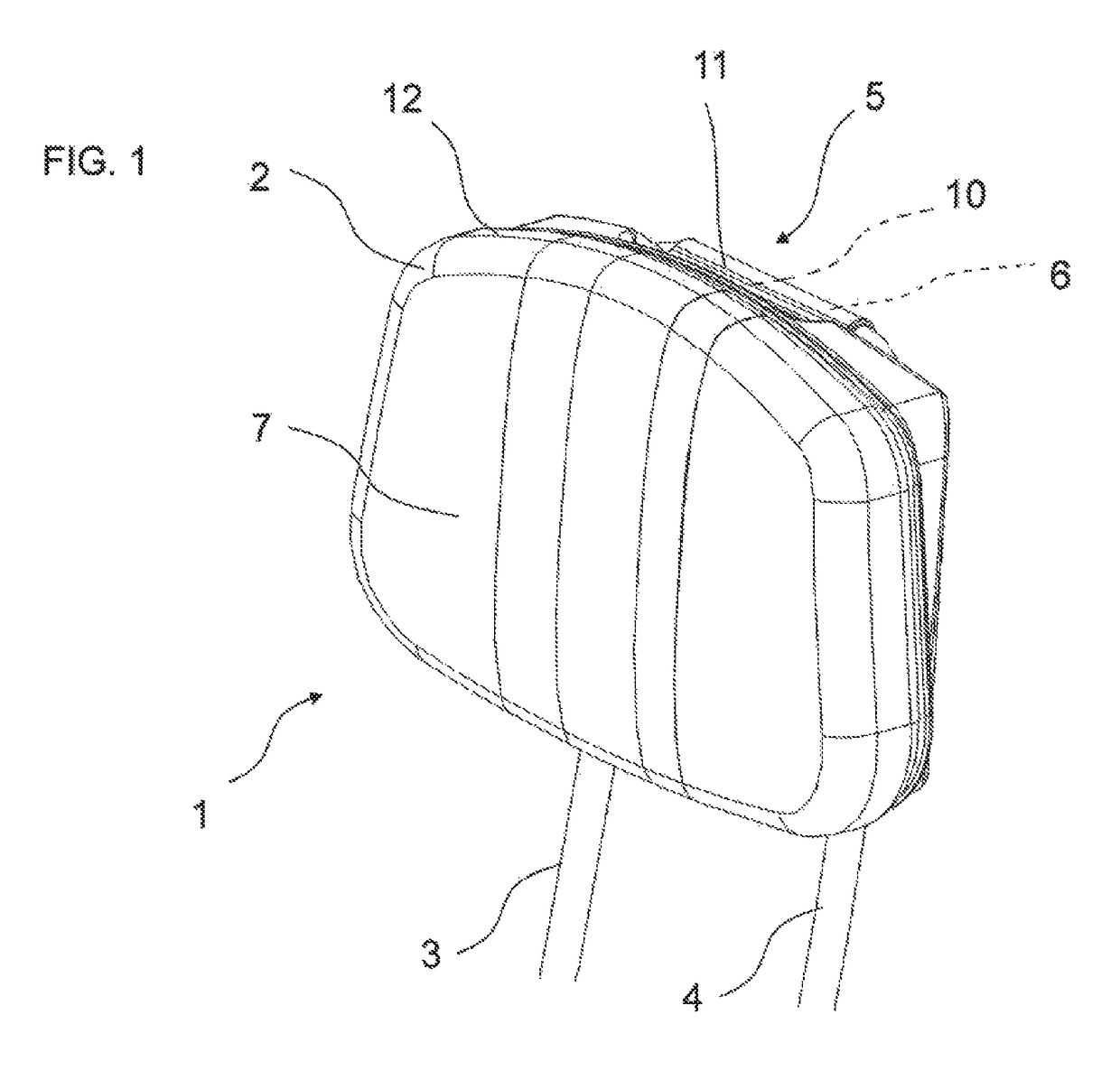
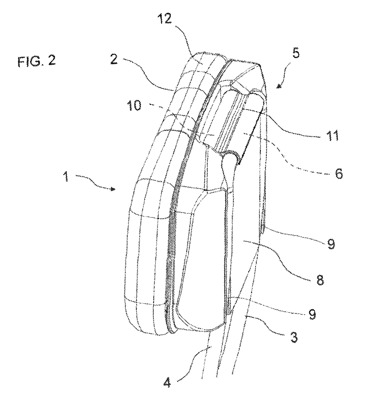
[0009]The embodiment of the headrest according to the invention allows an extremely simple and cost-effective design for realizing the turn-down function of the padded part, as the padded part only has to be suspended from the outside from the cross member in a swiveling movable manner. The overall mechanism of the turn-down device is limited accordingly to the cross member connected to the carrying bars and also the swiveling movable suspension of the padded part. Due to the simple mechanism, the headrest according to the invention is, moreover, extremely easy to operate, as the padded part can be turned down in the simplest manner by swiveling about the cross member of the carrying bars between the in-use position and the out-of-use position. Since the turn-down device of the headrest according to the invention is not attached within the padded part, the padded part may be configured in a manner substantially unrestricted by the swiveling mechanism, so that a comfortable and secure supporting function of the padded part can be guaranteed in its in-use position. In its out-of-use position in which the padded part is swiveled to the rear in the direction of a rear side of the backrest of the vehicle seat, it does not act as an obstacle to the fitting of a child-restraining system, for example a child seat, on the vehicle seat. Moreover, when the headrest is in the out-of-use position, the rear view for a driver of the vehicle is not restricted by the padded part.
[0010]An advantageous embodiment of the invention envisages that the carrying bars run along a rear side of the padded part and the padded part rests in its in-use position with its rear side against the carrying bars. In this way, the padded part is reliably positioned in its in-use position, without it requiring a costly locking mechanism for the padded part which, moreover, makes operation of the headrest significantly easier.
[0011]According to a further advantageous embodiment of the invention, recesses assigned to the carrying bars are provided on the rear side of the padded part, in which recesses the carrying bars run when the padded part is in the in-use position. The recesses are particularly preferably configured in such a manner that the carrying bars are completely housed therein, something that improves the aesthetic impact of the headrest, as the carrying bars do not project from the contour of the padded part on the rear side thereof.
[0012]A further advantageous embodiment of the invention envisages that the recesses display overpressable locking devices for the carrying bars. Consequently, the padded part can be locked and held in its in-use position on the carrying bars. The overpressable locking device can preferably be overcome with relatively little manual force, so that the operability of the headrest is not negatively affected by this. The overpressable locking device may, for example, be realized by a simple reduction in the clear width of the internal diameter of the recess in a certain longitudinal section of said recess. The reduction in the clear width of the recess acts on the carrying bar held therein as a flexible locking device, the elastic force whereof can be overcome manually by the user of the headrest when the carrying bars are inserted into the recess and also when the headrest is removed.
[0016]According to a further aspect, the invention comprises a vehicle seat with a backrest and a headrest arranged thereon, according to one of the previously described embodiments. The facility described above of moving the headrest into an out-of-use position means that an improved construction size of the vehicle seat can be achieved. Particularly in the out-of-use position of the headrest, the vehicle seat displays a more compact embodiment overall, as the vertical extension of the headrest in the out-of-use position is smallest, as a result of which the rear view for a driver of the vehicle is least restricted. Moreover, the swiveling of the headrest into the out-of-use position allows a child-restraining system, a child seat for example, to be securely fitted to the vehicle seat.
[0017]An advantageous embodiment of the vehicle seat according to the invention envisages that the carrying bars are housed in the backrest in a longitudinally displaceable manner, in other words the headrest is height-adjustable relative to the backrest. This makes operability during the swiveling of the padded part of the headrest, among other things, easier.

Problems solved by technology

The overall mechanism of the turn-down device is limited accordingly to the cross member connected to the carrying bars and also the swiveling movable suspension of the padded part.

Method used


Image

  • Foldable headrest with double hinge
  • Foldable headrest with double hinge
  • Foldable headrest with double hinge

Examples


Embodiment Construction

[0031]For purposes of description herein, the terms “upper,”“lower,”“right,”“left,”“rear,”“front,”“vertical,”“horizontal,” and derivatives thereof shall relate to the invention as oriented in FIG. 1. However, it is to be understood that the invention may assume various alternative orientations, except where expressly specified to the contrary. It is also to be understood that the specific devices and processes illustrated in the attached drawings, and described in the following specification are simply exemplary embodiments of the inventive concepts defined in the appended claims. Hence, specific dimensions and other physical characteristics relating to the embodiments disclosed herein are not to be considered as limiting, unless the claims expressly state otherwise.

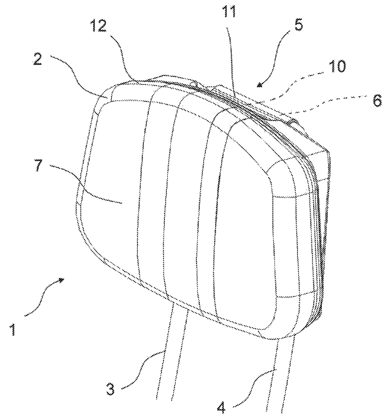
[0032]FIG. 1 depicts a perspective front view of an embodiment of a headrest 1 according to the invention for a vehicle seat of a motor vehicle not shown in FIG. 1 in an in-use position. As can be seen in FIG. 1, the hea...


PUM


Abstract

A headrest for a vehicle seat includes a padded part, carrying bars for securing the padded part to a backrest of the vehicle seat, and a mechanism for turning down the padded part about two swivel axes and from an in-use position into an out-of-use position. The mechanism comprises a cross member connecting the carrying bars to one another and forming the swivel axis of the padded part. Furthermore, the carrying bars and also the cross member run outside the padded part and the padded part is suspended on the cross member from the outside in a swiveling movable manner via the retaining strut and the double clip.

Description

CROSS-REFERENCE TO RELATED APPLICATION[0001]This application claims priority to DE 102014216322.6, filed on Aug. 18, 2014, the entire contents of which are hereby incorporated herein by reference.FIELD OF THE INVENTION[0002]The present invention relates to a headrest for a vehicle seat.BACKGROUND OF THE INVENTION[0003]It is known in the art that headrests, particularly on rear seats, or headrests attached to a rear bench seat in a motor vehicle can impede the fitting of a child-restraining system, for example a child seat. Insofar as the headrest is not removed for the fitting of the child seat in a case such as this, this can lead to improper use of the child seat in which correct positioning can no longer be guaranteed. In addition, it is generally accepted that headrests on the rear seats can restrict a driver's rear view significantly. For these reasons, headrests have been developed that can be turned down between an in-use position in which the headrest can provide support to ...

Claims


Application Information

Patent Timeline
Patent Type & Authority Patents(United States)
IPC IPC(8): B60N2/48
CPCB60N2/487B60N2/4808B60N2/4841B60N2/4855B60N2/4858B60N2/4873B60N2/4879B60N2002/4891B60N2/856B60N2/809B60N2/876B60N2/891B60N2/882B60N2/874B60N2/841B60N2/859
Inventor WAGNER, UWESCHAUF, CARSTENHARI, DANIELVAS, KILIAN
Owner FORD GLOBAL TECH LLC
Learn More