
Switch driving circuit, and power factor correction circuit having the same

a technology of power factor correction and driving circuit, which is applied in the direction of power conversion systems, pulse techniques, climate sustainability, etc., can solve the problems of reactive power loss, power loss, interference with other devices, etc., and achieve the effect of preventing circuit damag

Active Publication Date: 2017-09-12
SEOUL NAT UNIV R&DB FOUND +1
View PDF13 Cites 11 Cited by
  • Summary
  • Abstract
  • Description
  • Claims
  • Application Information

AI Technical Summary

Benefits of technology

This patent describes a circuit that prevents damage to electronic components when a switch is driven malfunctions. The circuit uses a special component called a Zener diode to create a negative offset. The technical effect of this circuit is to increase the reliability and durability of electronic circuits.

Problems solved by technology

When the power factor of an AC power system is not equal to 1, a current waveform may not follow the voltage waveform, thereby potentially causing power loss as well as occurrence of harmonics that pass the AC power system, which interferes with other devices.
It is rare for the load that is connected to a power source to only have pure resistance components, but the load often has a capacitive or inductive components, which cause reactive power loss.
Especially, in case of converting AC power to DC power for use, a smoothing capacitor is used to reduce the AC components, which may cause the power factor to be reduced.

Method used


Image

  • Switch driving circuit, and power factor correction circuit having the same
  • Switch driving circuit, and power factor correction circuit having the same
  • Switch driving circuit, and power factor correction circuit having the same

Examples


Embodiment Construction

[0043]Reference will now be made in detail to the embodiments, examples of which are illustrated in the accompanying drawings, wherein like reference numerals refer to the like elements throughout. The embodiments are described below to explain the present invention by referring to the figures.

[0044]Advantages, features, and methods for achieving them will be understood more clearly when the following embodiments are read with reference to the accompanying drawings.

[0045]Embodiments and features as described and illustrated in the present disclosure are only preferred examples, and various modifications thereof may also fall within the scope of the disclosure.

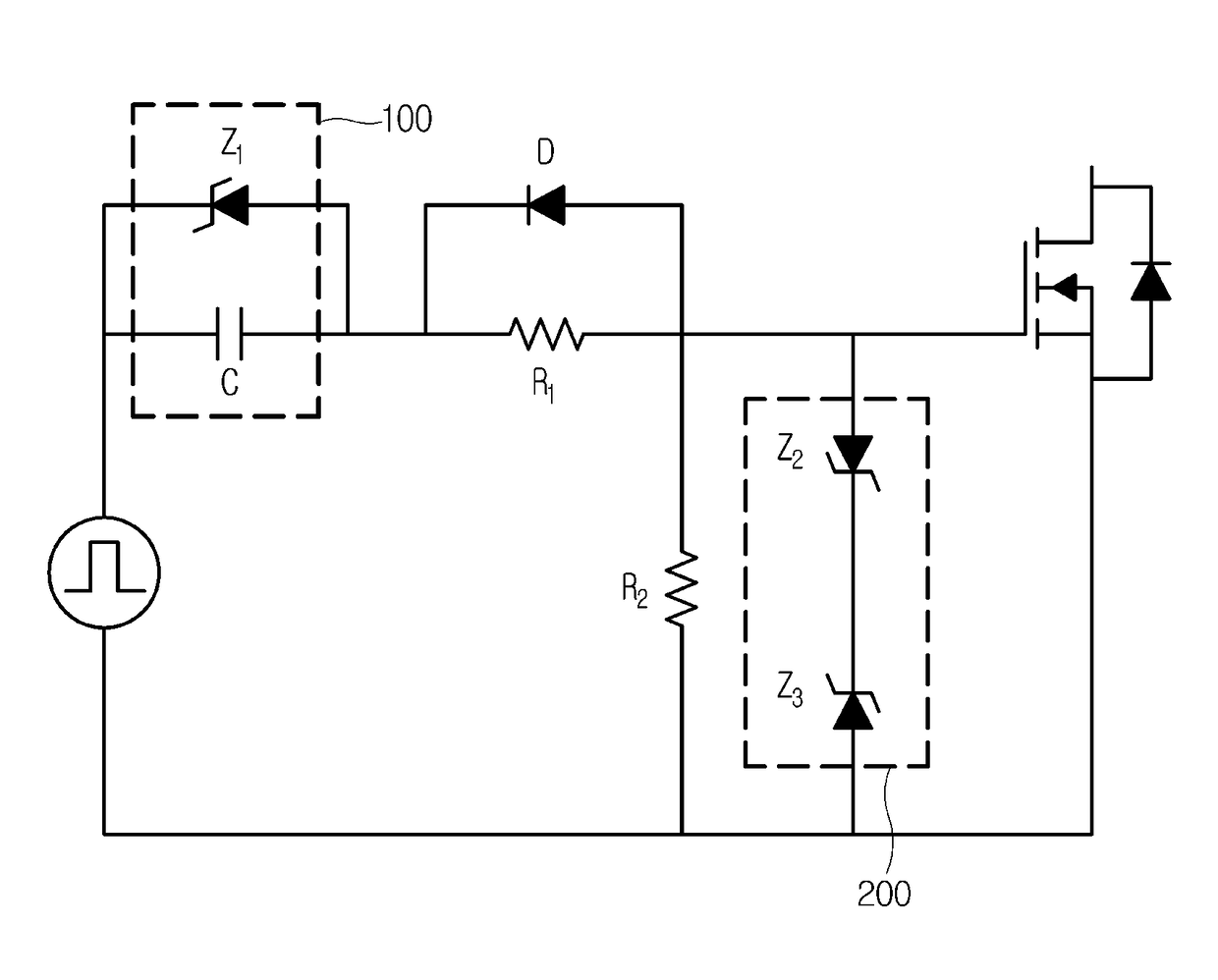
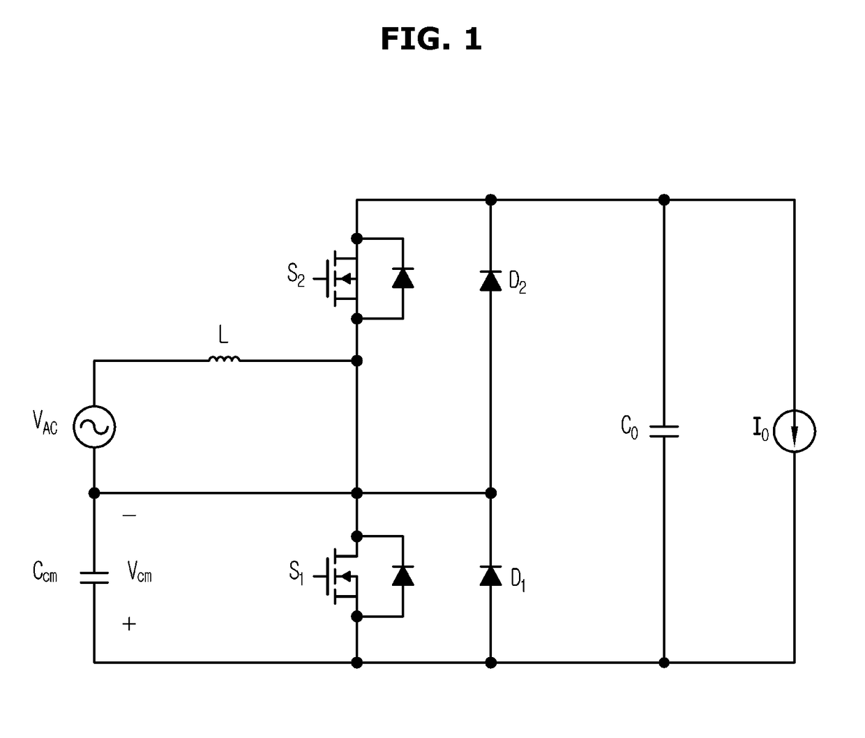
[0046]Embodiments of a switch driving circuit and power factor correction (PFC) circuit having the same will be described below. Furthermore, an electronic product equipped with a PFC circuit having the switch driving circuit will also be described. Like reference numerals refer to like components throughout the drawings, and t...


PUM


Abstract

The present disclosure relates generally to a switch driving circuit and power factor correction circuit having the same, and more particularly, to a technology to provide a negative offset using Zener diodes to prevent malfunctions in driving a switch. The switch driving circuit to operate a switch implemented with a Field Effect Transistor (FET) includes a first Zener diode connected to a control input end of the switch; a capacitor connected in parallel with the first Zener diode; and second and third Zener diodes for providing a negative offset to fix a voltage applied between the gate and source of the switch to a negative value.

Description

CROSS-REFERENCE TO RELATED APPLICATIONS[0001]This application claims the benefit under 35 U.S.C. §119(a) of a U.S. provisional patent application filed on Mar. 27, 2015 in the US Patent and Trademark Office and assigned Ser. No. 62 / 139,141 and claims benefit of foreign priority to Korean patent application filed on Aug. 18, 2015 in the Korean Intellectual Property Office and assigned Ser. No. 10-2015-0116091, the entire disclosures of which are incorporated hereby incorporated by reference.BACKGROUND[0002]1. Field[0003]The present disclosure relates generally to a switch driving circuit and power factor correction circuit having the same, and more particularly, to a technology to provide a negative offset using Zener diodes to prevent malfunctions in driving a switch.[0004]2. Description of Related Art[0005]The power factor of an Alternate Current (AC) electrical power system is defined as the ratio of the real power flowing to the load to the apparent power.[0006]This is also refer...

Claims


Application Information

Patent Timeline
Patent Type & Authority Patents(United States)
IPC IPC(8): H03K17/687H02M1/42H03K17/16H03K17/30
CPCH02M1/4208H02M1/4225H03K17/162H03K17/302Y02B70/126Y02B70/10H02M1/0085
Inventor KIM, JIN HANSEO, HAN SOLCHO, BO-HYUNGKANG, SANG-WOOJANG, PAUL
Owner SEOUL NAT UNIV R&DB FOUND
Learn More