
Synchronized multiple-radio antenna systems and methods

a technology of antenna system and antenna system, applied in the direction of antenna support/mounting, radio transmission, transmission, etc., can solve the problems of requiring a significant amount of tower space and therefore expense, slowing and inefficiency of the resulting antenna system, and high cost of radio tower spa

Active Publication Date: 2017-09-12
UBIQUITI INC
View PDF106 Cites 13 Cited by
  • Summary
  • Abstract
  • Description
  • Claims
  • Application Information

AI Technical Summary

Benefits of technology

The present invention relates to methods and apparatuses for combining multiple radio frequencies (RF) radios so that they can simultaneously send or receive RF signals from a single antenna. The methods involve passively combining the inputs of each RF radio into a single output coupled to the antenna, synchronizing each RF radio using a global synchronization signal, transmitting RF signals from each RF radio in a synchronized manner, and receiving RF signals in each RF radio in a synchronized manner. The methods and apparatuses can be used in MIMO mode and may not require communication between the radios. The technical effects of the invention include improved synchronization and more efficient use of multiple RF radios in a shared antenna system.

Problems solved by technology

Space in radio towers is often at a premium, and may be expensive.
Each antenna requires space and separation from other antenna to prevent undesirable interference, requiring a significant amount of tower space and therefore expense.
Although antenna systems in which more than one radio may be used, these systems typically require a great deal of coordination and communication between each radio of the system, resulting a slowing and inefficiencies of the resulting antenna system and also increased cost.
Further, such systems are not well able to adapt to changes in the transmission rate (or disruption of) one or more of the radios.
It is also possible to use lumped inductor and capacitor elements, but this complicates the overall design.
Although the cost may otherwise be very low, to reduce losses, a low-loss PCB substrate may be used, which may increase the cost.
Loss may arise from the division of the power between the different ports, though components used for a Wilkinson splitter can be relatively low loss, especially when PCB transmission lines are used along with low-loss PCB substrate materials.
Disadvantages of traditional Wilkinson splitters may include a reduction in frequency response.

Method used


Image

  • Synchronized multiple-radio antenna systems and methods
  • Synchronized multiple-radio antenna systems and methods
  • Synchronized multiple-radio antenna systems and methods

Examples


examples

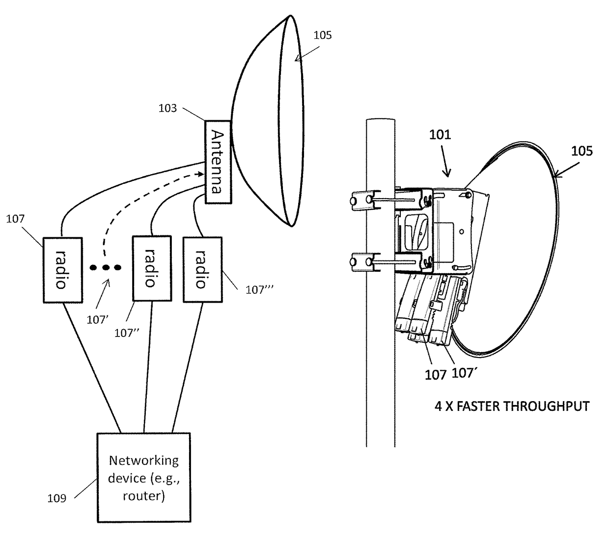
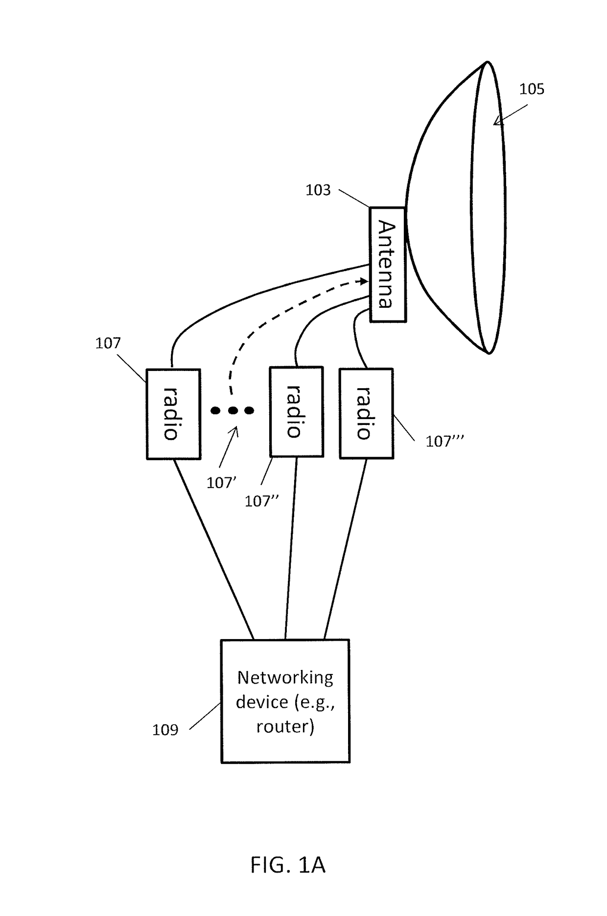
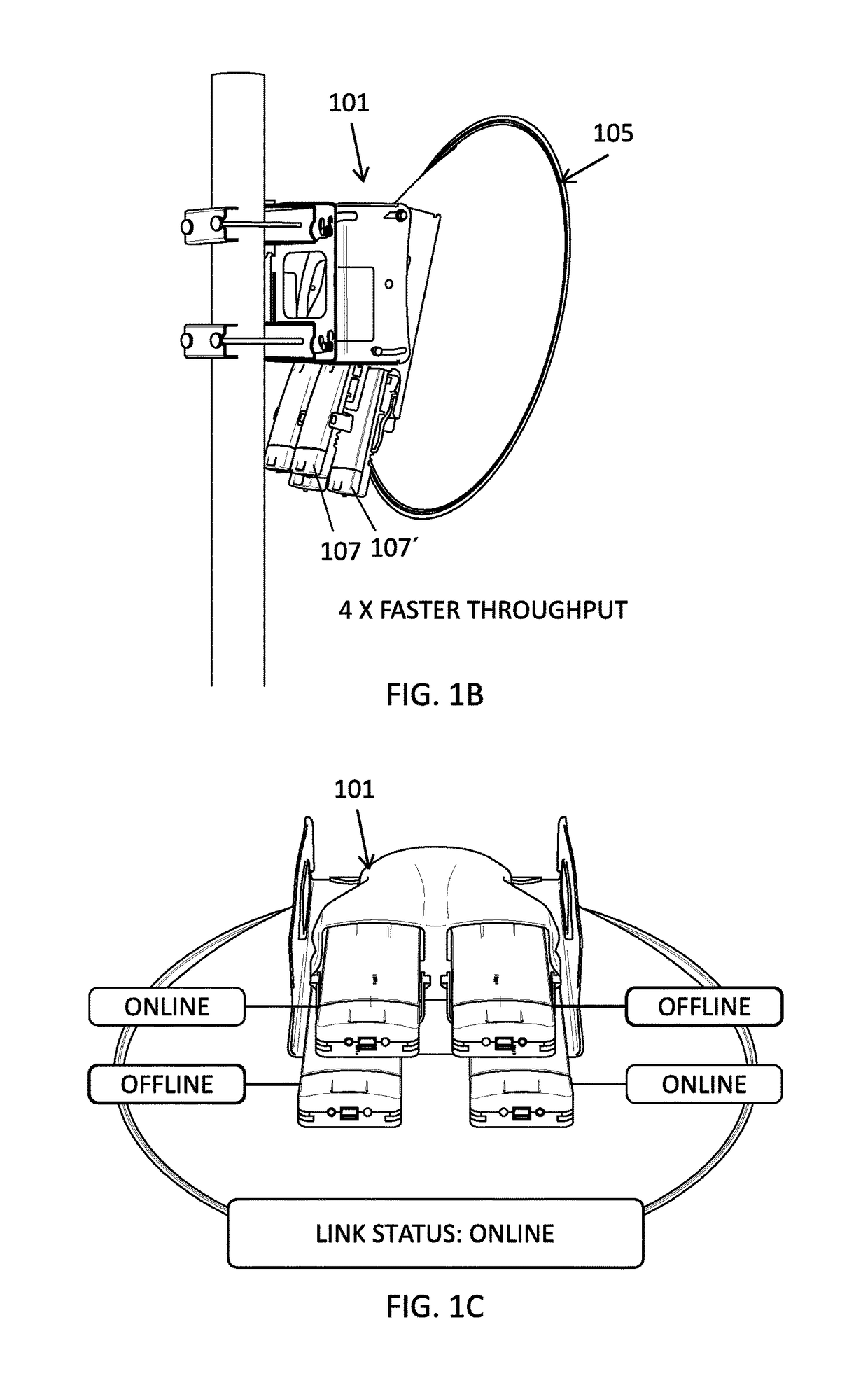
[0064]In some embodiments of the methods and apparatuses described herein, the apparatus is a scalable MIMO Multiplexer having a very reduced footprint because it can efficiently combine multiple radios with a single antenna (e.g., in some variations a single reflector). FIGS. 1B-1D illustrate examples of such a multiplexing apparatus, which may be referred to as an “N×N” MIMO multiplexer. This apparatus may have multi-gigabit throughput, and also allows redundancy between the included radios, without the need for additional antennas. Each of the radios may transmit synchronously and receive synchronously. Because they are synchronized and their RF signals passively mixed by the multiplexer, they may simultaneously communicate from the same antenna with very little Rx degradation / interference (e.g., cross-talk, etc.); each radio may transmit at a different frequency band, and these bands may be immediately adjacent, without the need for a guard band between nearby frequency bands.

[0...


PUM


Abstract

Multi-radio antenna apparatuses and stations for wireless networks including multiple radios coupled to a single transmit / receive antenna, in which the antenna is highly synchronized by an external (e.g., GPS) signal. These multi-radio antenna systems may provide highly resilient links. Synchronization may allow these apparatuses to organically scale the transmission throughput while preventing data loss. The single transmit / receive antenna may have a single dish or a compound (e.g., a single pair of separate transmitting and receiving dishes) and connections for two or more radios.

Description

CROSS REFERENCE TO RELATED APPLICATIONS[0001]This patent application claims priority to U.S. Provisional Patent Applications No. 62 / 239,831, titled “SYNCHRONIZED MULTIPLE-RADIO ANTENNA SYSTEMS AND METHODS”, filed on Oct. 9, 2015, and U.S. Provisional Patent Applications No. 62 / 277,862, titled “SYNCHRONIZED MULTIPLE-RADIO ANTENNA SYSTEMS AND METHODS” filed on Jan. 12, 2016, each of which is herein incorporated by reference in its entirety.INCORPORATION BY REFERENCE[0002]All publications and patent applications mentioned in this specification are herein incorporated by reference in their entirety to the same extent as if each individual publication or patent application was specifically and individually indicated to be incorporated by reference.FIELD[0003]The apparatuses described herein generally relate to antenna having multiple radios connected to a single emitter / receiver for simultaneous transmission from each of the radios. The radios may be balanced (e.g., data packet load bala...

Claims


Application Information

Patent Timeline
Patent Type & Authority Patents(United States)
IPC IPC(8): H04B15/00H01Q19/10H01Q15/16H01Q21/00H01Q1/24
CPCH01Q19/10H01Q1/24H01Q15/16H01Q21/00H01Q1/50H01Q19/12H04B7/0413H01Q19/13H04B1/00
Inventor KENIUK, RICHARD J.SCHULZ, GARY D.
Owner UBIQUITI INC
Learn More