
Shooting apparatus including a diaphragm

a diaphragm and shooting apparatus technology, applied in the field of shooting apparatus and camera system, can solve the problem of limited diaphragm stop range in actual shooting, and achieve the effect of improving usability and reducing the movement of the focusing position

Active Publication Date: 2017-09-05
OM DIGITAL SOLUTIONS CORP
View PDF13 Cites 1 Cited by
  • Summary
  • Abstract
  • Description
  • Claims
  • Application Information

AI Technical Summary

Benefits of technology

The present invention aims to provide a shooting apparatus and a camera system that can prevent the focusing position from moving when adjusting the diaphragm stop, regardless of the actual diaphragm stops. This improvement will make the use of the camera system simpler and more intuitive for users.

Problems solved by technology

However, the range of the diaphragm stops is limited in actual shooting.

Method used


Image

  • Shooting apparatus including a diaphragm
  • Shooting apparatus including a diaphragm
  • Shooting apparatus including a diaphragm

Examples


Embodiment Construction

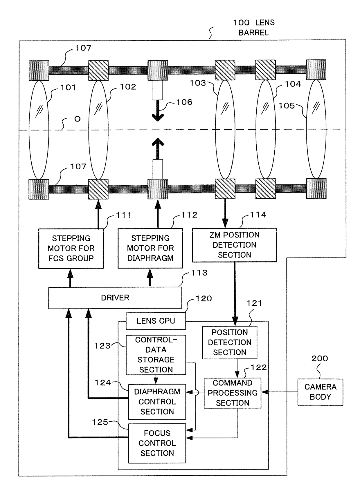
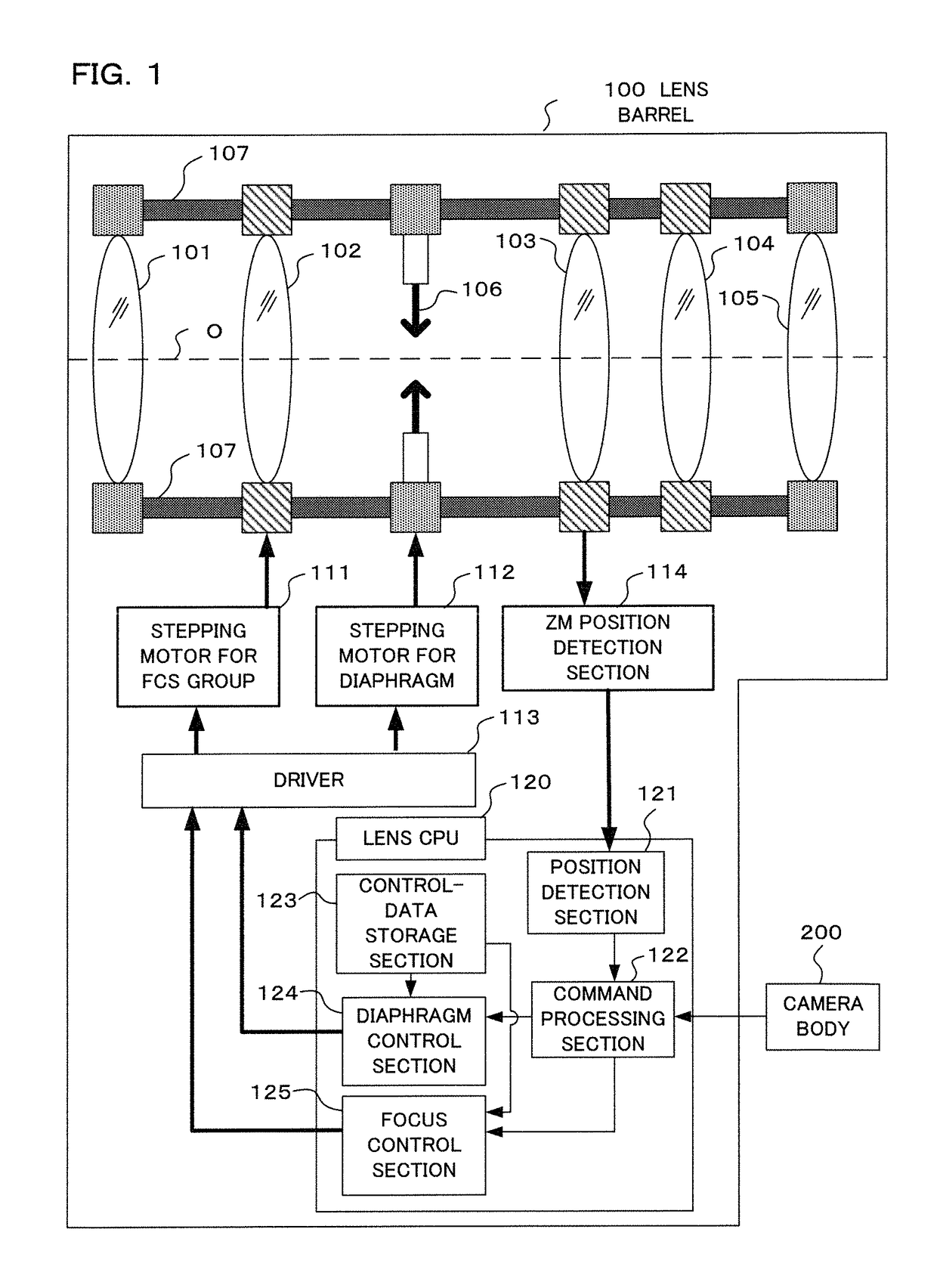
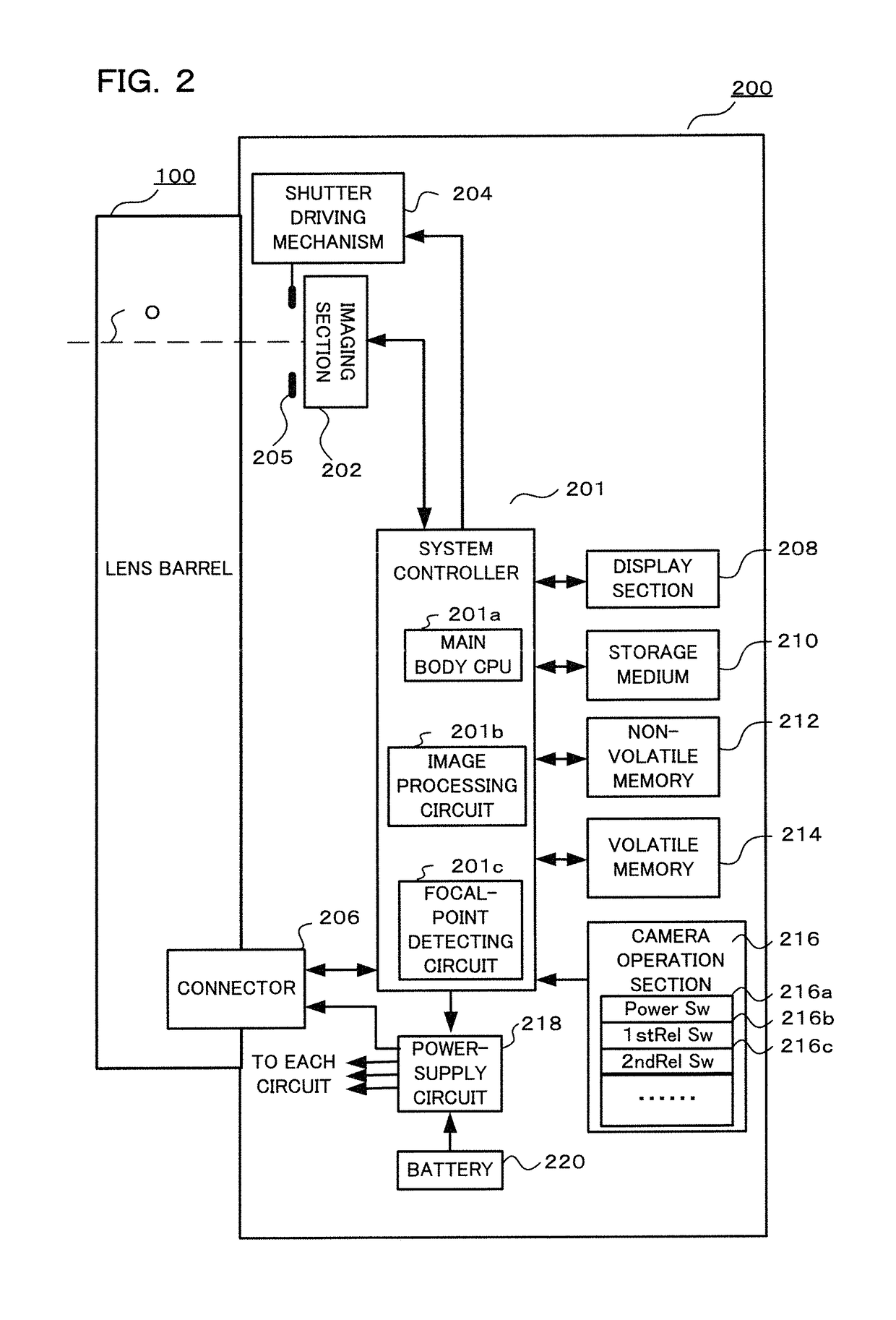
[0046]Hereinbelow, description will be made of an example of an embodiment according to the present invention, in which the present invention is applied to a digital camera as an embodiment of the present invention. This digital camera includes a photographing optical system having a variable aperture diaphragm, and an imaging section. This imaging section converts a subject image into image data. On the basis of the converted image data, the subject image is displayed on a display section disposed on the back surface of the main body as a through image. A photographer views the through image display to determine the composition and shutter timing. At the time of a release operation, the image data is recorded in a recording medium. Upon selection of a reproduction mode, the image data recorded in the recording medium can be reproduced on the display section.

[0047]FIG. 1 is a block diagram illustrating a configuration of a lens barrel 100 of the camera according to an embodiment of ...


PUM


Abstract

A shooting apparatus comprising: a photographing optical system having a variable aperture diaphragm; an imaging section that outputs an image signal; a diaphragm position detection section that detects a diaphragm position; a lens control section that controls movement of a focus lens; a storage section that stores an amount of focal shift corresponding to the diaphragm position; a focus detection section that detects a peak of a contrast value based on the image signal, wherein the lens control section, while moving the focus lens to a focusing position based on a position at which the contrast value indicates the peak, corrects a position of the focus lens to be moved, on the basis of a diaphragm position when the position at which the contrast value indicates the peak is detected, a diaphragm position while moving the focus lens, and the amount of focal shift stored in the storage section.

Description

[0001]Benefit is claimed, under 35 U.S.C. §119, to the filing date of prior Japanese Patent Application No. 2014-227944 filed on Nov. 10, 2014. This application is expressly incorporated herein by reference. The scope of the present invention is not limited to any requirements of the specific embodiments described in the application.BACKGROUND OF THE INVENTION[0002]1. Field of the Invention[0003]The present invention relates to a shooting apparatus and a camera system capable of performing in-focus shooting, even if the focusing position changes due to a change in the diaphragm opening amount, in the shooting apparatus having a diaphragm provided within a photographing optical system.[0004]2. Description of Related Art[0005]A focusing operation for a photographing optical system is performed in a state where the diaphragm is open, and then, actual shooting is performed after the diaphragm is stopped down to a diaphragm stop that can achieve appropriate exposure, or to a set diaphrag...

Claims


Application Information

Patent Timeline
Patent Type & Authority Patents(United States)
IPC IPC(8): G03B13/00H04N5/232H04N5/238G03B13/36H04N5/225G02B5/00G03B9/02G02B7/38H04N23/75
CPCH04N5/238G02B5/005G03B13/36H04N5/2254H04N5/23212G02B7/38G03B9/02G02B7/36H04N23/55H04N23/673H04N23/631H04N23/75
Inventor TAGUCHI, YUZURU
Owner OM DIGITAL SOLUTIONS CORP
Learn More