
Fuel supply apparatus for engine

a technology for fuel supply apparatus and general purpose engines, which is applied in the direction of machines/engines, carburetors, and feed systems, etc., can solve the problems of engine completely stopping, air-fuel mixture remaining unburned in the engine and muffler, and temporary ignition, so as to prevent the occurren

Active Publication Date: 2017-09-05
HONDA MOTOR CO LTD
View PDF14 Cites 0 Cited by
  • Summary
  • Abstract
  • Description
  • Claims
  • Application Information

AI Technical Summary

Benefits of technology

The present invention aims to prevent occurrence of afterburn in a cost-effective way by using an improved fuel supply apparatus. The technical effects of the invention include: a simple and less costly mechanical construction, prevention of fuel evaporative emission, and minimization of dissipation of fuel evaporative emission from the engine to the atmosphere. The fuel supply apparatus includes a passage switching section that can switch between a first communication passage and a second communication passage, mechanical connection to the main switch, and a three-way valve that can operate in interlocked relation to the main switch.

Problems solved by technology

However, due to inertia, the engine completely stops after having continued rotation for a certain time.
If an air-fuel mixture is supplied from the Venturi section of the carburetor to the engine during the idling, there can occur a so-called afterburn in which the air-fuel mixture remains unburned in the engine and muffler and temporarily ignites.
Thus, employing the multiplicity of electric component parts in such an inexpensive general-purpose engine would lead a great ratio of the total cost of the electric component parts to the overall cost of the entire general-purpose engine.
Because employing the multiplicity of electric component parts becomes a cause for a cost increase of the general-purpose engine, the fuel supply apparatus disclosed in the relevant patent literature is yet to be improved.

Method used


Image

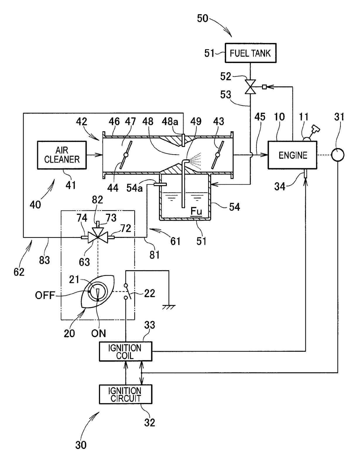
  • Fuel supply apparatus for engine
  • Fuel supply apparatus for engine
  • Fuel supply apparatus for engine

Examples


Embodiment Construction

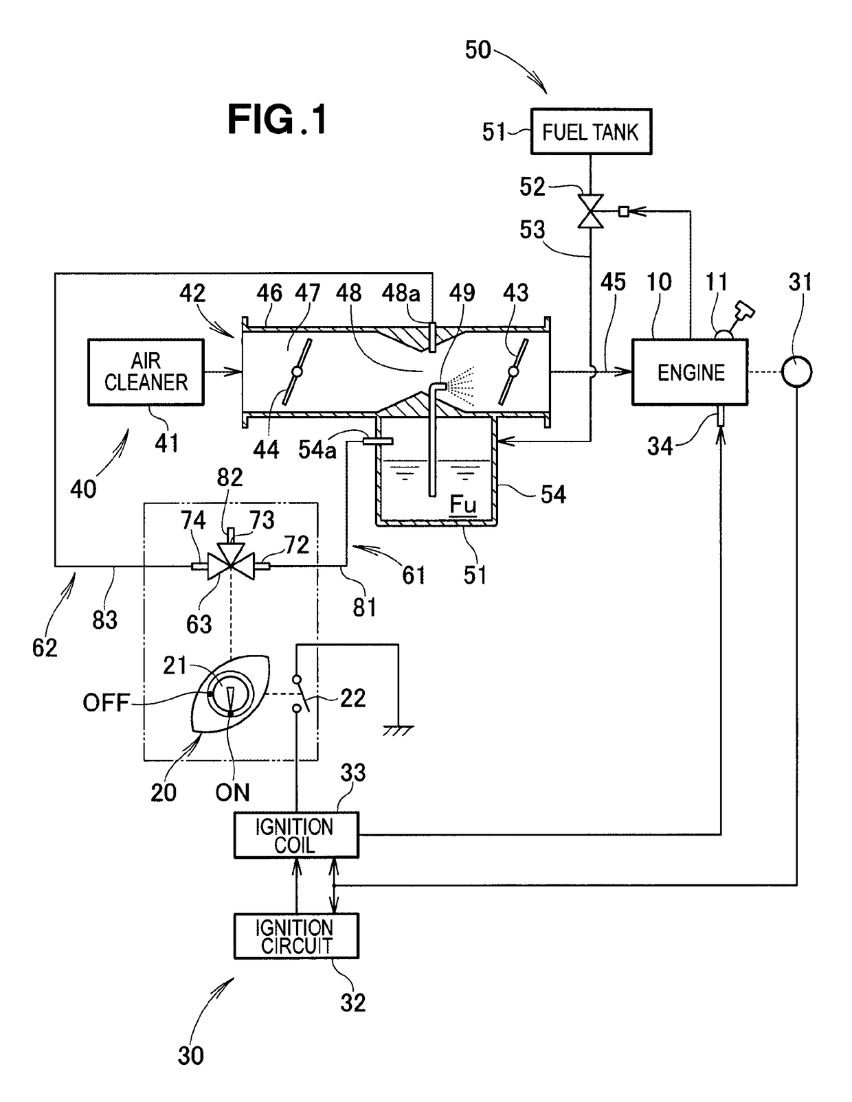
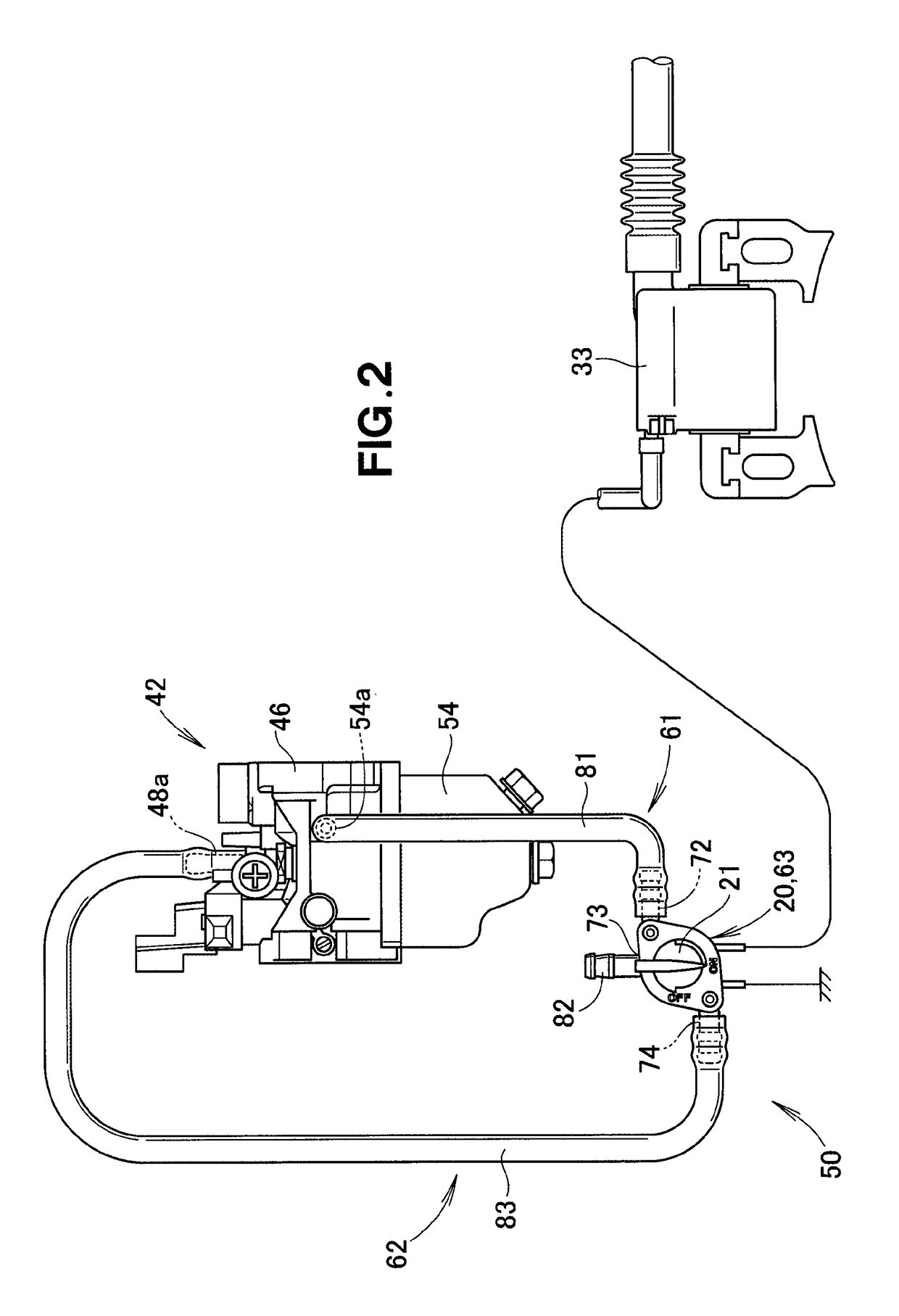
[0022]Now, an embodiment of a fuel supply apparatus for an engine (engine fuel supply apparatus) according to the present invention will be described with reference to the accompanying drawings.

[0023]As shown in FIG. 1, the engine 10 is, for example, a transversely-oriented, single-cylinder, two-cycle general-purpose engine. The “general-purpose engine” is a generic term for internal combustion engines provided on various working machines, such as electric power generators, pumps, outboard engines, agricultural working machines, civil engineering machines and transport vehicles. The engine 10 includes a recoil starter 11, a main switch 20, an engine ignition device 30, an engine air intake device 40, and the engine fuel supply apparatus 50.

[0024]The recoil starter 11 is an activation device operable by a human operator to manually activate the engine 10, and the recoil starter 11 is provided on a crankshaft of the engine 10 or on a flywheel connected directly to the crankshaft.

[0025...


PUM


Abstract

An engine fuel supply apparatus includes: a fuel chamber provided in a carburetor; a first communication passage for opening the interior of the fuel chamber to the atmosphere; a second communication passage for communicating the interior of the fuel chamber with the interior of a Venturi section; and a passage switching section capable of switching between the first and second communication passages and mechanically connected to the main switch so that it can operate in response to the main switch shifting between an ignition position and a stop position. The passage switching section switches the second communication passage to the first communication passage in response to the main switch shifting from the stop position to the ignition position and switches the first communication passage to the second communication passage in response to the main switch shifting from the ignition position to the stop position.

Description

FIELD OF THE INVENTION[0001]The present invention relates a fuel supply apparatus for a general-purpose engine.BACKGROUND OF THE INVENTION[0002]In general, where an ordinary general-purpose engine is employed in a working machine or the like, the engine is deactivated or stopped by a human operator operating a main switch to a stop position to turn off an ignition device. Negative pressure in the interior of a Venturi section of a carburetor is canceled by the deactivation of the engine. As a consequence, fuel spray from a fuel chamber, provided in the carburetor, into the Venturi section is stopped.[0003]However, due to inertia, the engine completely stops after having continued rotation for a certain time. Namely, some idling time is required before the engine completely stops. If an air-fuel mixture is supplied from the Venturi section of the carburetor to the engine during the idling, there can occur a so-called afterburn in which the air-fuel mixture remains unburned in the eng...

Claims


Application Information

Patent Timeline
Patent Type & Authority Patents(United States)
IPC IPC(8): F02M19/06F02D9/02F02M37/00F02M17/38
CPCF02M19/06F02D2009/0201F02M17/38F02M37/0023
Inventor ARAI, TETSUYAHONMA, KATSUKIANDO, MASAKI
Owner HONDA MOTOR CO LTD
Learn More