
Heat flux sensor with increased resolution

a technology of heat flux and sensor, applied in the field of heat flux sensor, can solve the problems of inability to reduce the size of the sensor, the sensor is less sensitive in terms of measurement of concentration for very light and/or volatile molecules, and the quantity of ions produced is always small

Active Publication Date: 2017-08-29
COMMISSARIAT A LENERGIE ATOMIQUE ET AUX ENERGIES ALTERNATIVES
View PDF15 Cites 0 Cited by
  • Summary
  • Abstract
  • Description
  • Claims
  • Application Information

AI Technical Summary

Benefits of technology

The present invention provides a heat flux sensor with improved resolution, using nanowires to insulate the membrane and reduce heat leakage. The sensor has a large heat exchange surface with the gas, making it more sensitive to the gas' nature. Additionally, the second current source delivers a lower current to prevent self-heating in the second membrane. Overall, this sensor is simple to produce and occupies a small volume.

Problems solved by technology

Firstly, this sensor allows detection only of organic components.
Secondly, it requires a hydrogen stream, and the quantity of ions produced is always small.
Finally, the size of the sensor cannot be reduced.
These sensors are ultra-sensitive for large gaseous molecules, but are less sensitive in terms of measurement of concentration for very light and / or volatile molecules.
But in order to be able to detect other types of gas the number of laser sources must be increased, which would greatly increase the complexity and cost of such a device.
These sensors are also difficult to miniaturise.
Macroscopic sensors are relatively insensitive.
Sensors of micrometric or nanometric size, for their part, suffer from problems of drift, i.e. chronological drift of the signal independent of the phenomenon to be measured, and from extreme sensitivity to the initial surface states.
This represents a major limitation of the detector.
This sensor is complex to produce since it requires that the bracket is manufactured, and then that the heating element and the electrical connections between the heating element and the substrate are produced.
In addition it is relatively bulky.

Method used


Image

  • Heat flux sensor with increased resolution
  • Heat flux sensor with increased resolution
  • Heat flux sensor with increased resolution

Examples


Embodiment Construction

[0017]It is consequently one aim of the present invention to provide a heat flux sensor with improved resolution, which is simple to produce and which occupies a small volume.

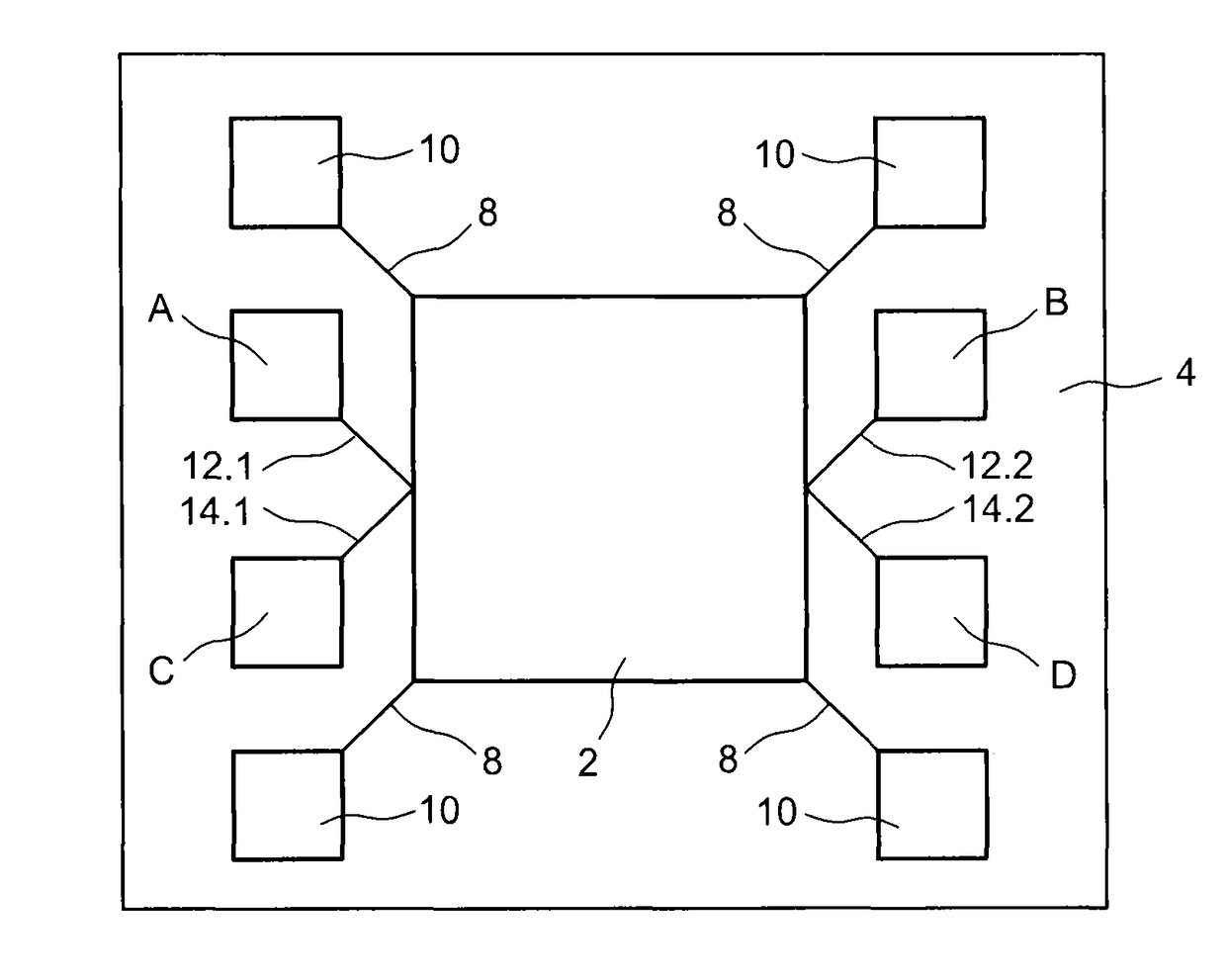
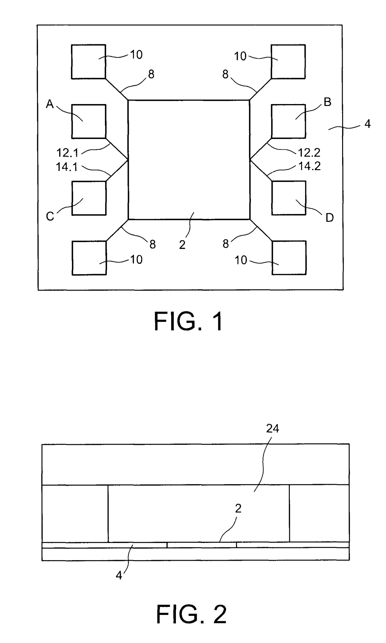
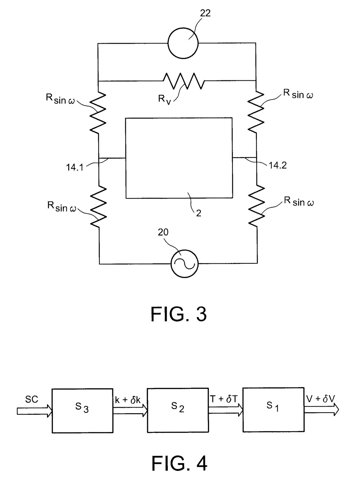
[0018]The declared aim is achieved by a heat flux sensor comprising at least one membrane suspended relative to a substrate by nanowires, where means of heating and polarising the membrane formed by nanowires connect the membrane to at least one current source, and means of measuring the electrical voltage at the membrane's terminals.

[0019]The voltage measuring means may be formed by nanowires connecting the membrane and a voltmeter.

[0020]Use of nanowires between the membrane and the substrate provides thermal insulation of the membrane relative to the substrate, which limits the heat leakages via the membrane's suspension means, and makes the device more sensitive to the heat leakages occurring due to the gas.

[0021]The heating nanowires and the polarisation nanowires and nanowires for measuring the voltage var...


PUM

PropertyMeasurementUnit
thickaaaaaaaaaa
thickaaaaaaaaaa
temperature coefficient of resistanceaaaaaaaaaa

Abstract

A heat flux sensor comprising at least one support, where at least one membrane is suspended relative to the support by at least four nanowires, where the membrane is made from at least one current-conducting material, and where the nanowires are made from a current-conducting material, with two nanowires connected to a current source to polarize the membrane between two terminals and a heater for heating the membrane, and where two nanowires are connected to a voltmeter to form measure the voltage at the terminals of the membrane.

Description

TECHNICAL FIELD AND PRIOR ART[0001]The present invention relates to a heat flux sensor, and to a system for determining the concentration of the components of a gas from its thermal and fluid characteristics, comprising at least one such sensor.[0002]A heat flux sensor is understood to mean any sensor measuring a heat exchange between the body of the sensor, for example a membrane, and the fluid medium in which the sensor is positioned. This heat flux sensor is, for example, a gas sensor, in particular of the TCD type (Thermal Conductivity Detector), or a pressure sensor, notably of the Pirani gauge type.[0003]This type of sensor may be positioned at the outlet of a chromatography column, more specifically a chromatography microcolumn, where the latter enables the different gaseous elements of a complex blend to be separated chronologically. The sensor is used to quantify the relative concentration of the analytes of the gas to be analysed which arrive in succession at its surface. ...

Claims


Application Information

Patent Timeline
Patent Type & Authority Patents(United States)
IPC IPC(8): G01N25/18G01N30/66G01K17/06G01N27/18
CPCG01K17/06G01N27/18G01N30/66
Inventor RUELLAN, JEREMIEDURAFFOURG, LAURENT
Owner COMMISSARIAT A LENERGIE ATOMIQUE ET AUX ENERGIES ALTERNATIVES
Learn More