
Pressure relief valve

a pressure relief valve and valve body technology, applied in the field of pressure relief valves, can solve the problems of direct affecting the ability of the pressure relief valve to keep within the original calibrated parameters, weak component breakage, system breakdown, etc., and achieves the effect of preventing seal distortion, easy reset, and inherent corrosive and abrasive properties

Active Publication Date: 2017-08-22
MARATHON VALVE LLC
View PDF13 Cites 5 Cited by
  • Summary
  • Abstract
  • Description
  • Claims
  • Application Information

AI Technical Summary

Benefits of technology

The patent text describes various improvements made to a valve design to improve its functionality and allow for consistent performance. These improvements include adding coatings and low friction material to keep the valve's level of friction consistent, adding a hard coating to the piston to prevent damage from abrasive fluids, using a low friction material for the stem bushing insert to prevent distortion, maintaining the proper shape and integrity of the seal to prevent leakage, and designing a sub to reduce galling and improve fluid discharge. Additionally, the patent discusses the use of a uni-body construction for the lower link to ensure smooth movement and prevent false opening of the valve. Overall, these technical improvements enhance the valve's performance and reliability in various industrial applications.

Problems solved by technology

In such systems, overpressure can damage valuable processing equipment, cause rupture of weak components, and / or a breakdown of the system.
In carrying out the rapid opening of the pressure relief valve and contact with process fluids, elements within the pressure relief valve, such as the seals and piston, are affected by friction within the pressure relief valve which directly affects the ability of the pressure relief valve to keep within its original calibrated parameters.

Method used


Image

  • Pressure relief valve
  • Pressure relief valve
  • Pressure relief valve

Examples


Embodiment Construction

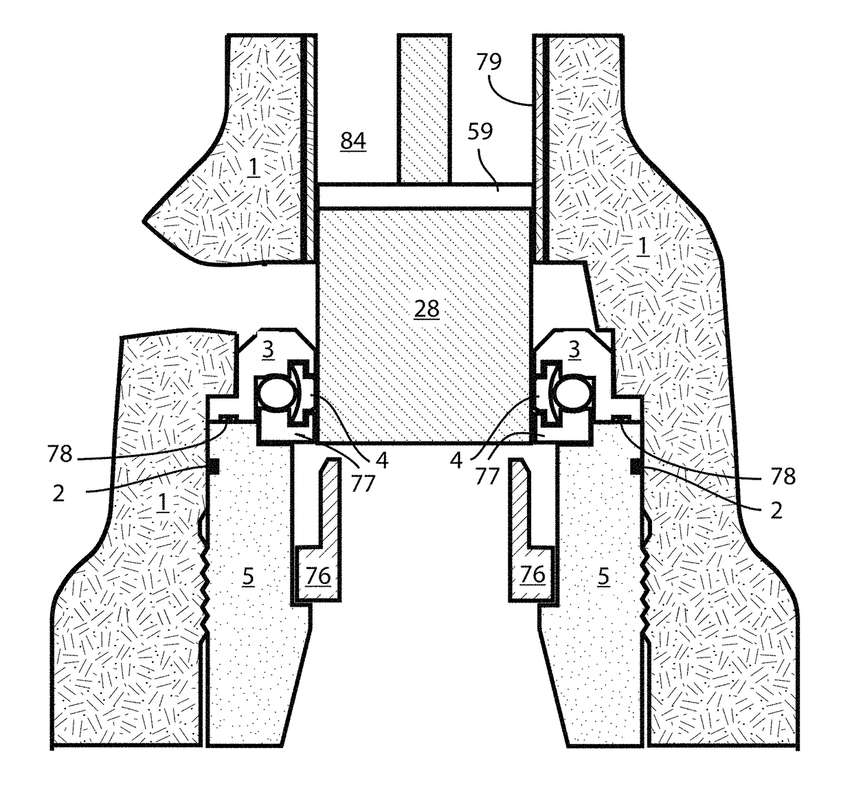
[0027]A new pressure relief valve sustains its original calibration after opening several times in a normal operating environment, overcoming the problems set forth above. The components of the new pressure relief valve are not damaged by the pressure relief valve opening allowing the seals and other components involved in maintaining the sealing and opening action to keep the same resistance in the movement of the valve opening. As the pressure relief valve moves from a fluid blocking position to an open position, that seals and components exposed to fluid being discharged are protected from the fluid's abrasive characteristics.

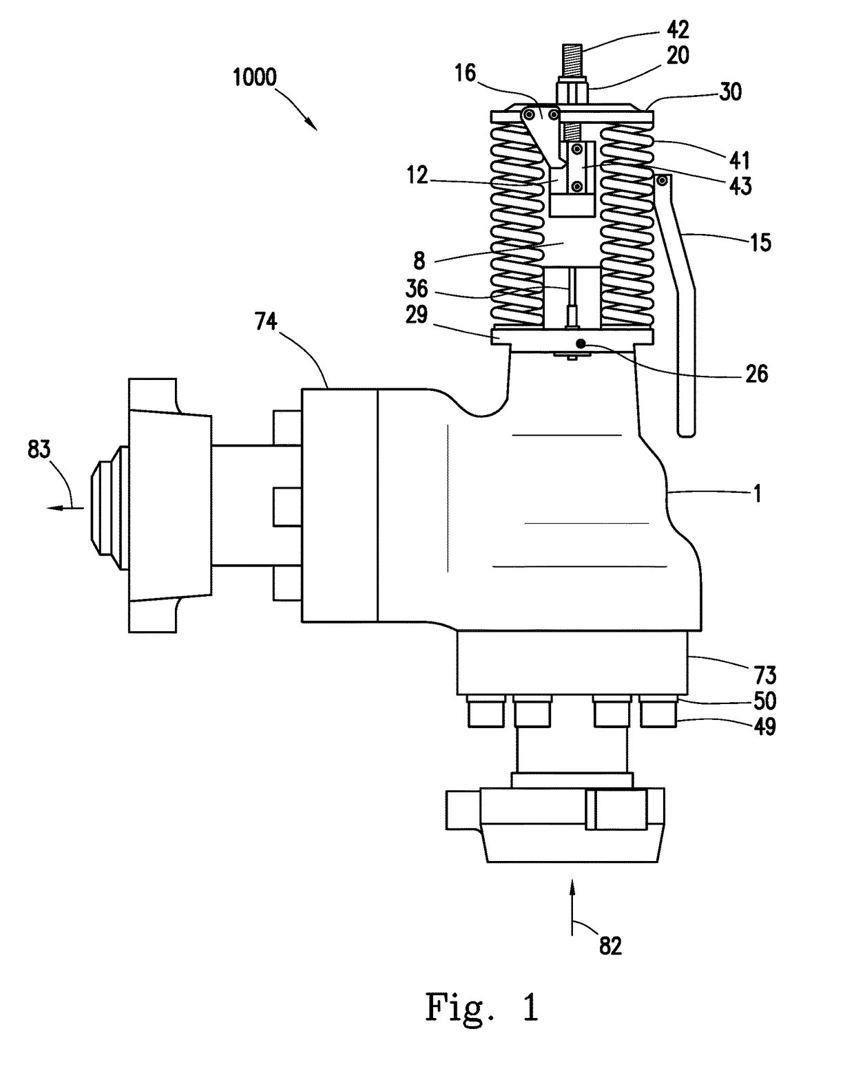
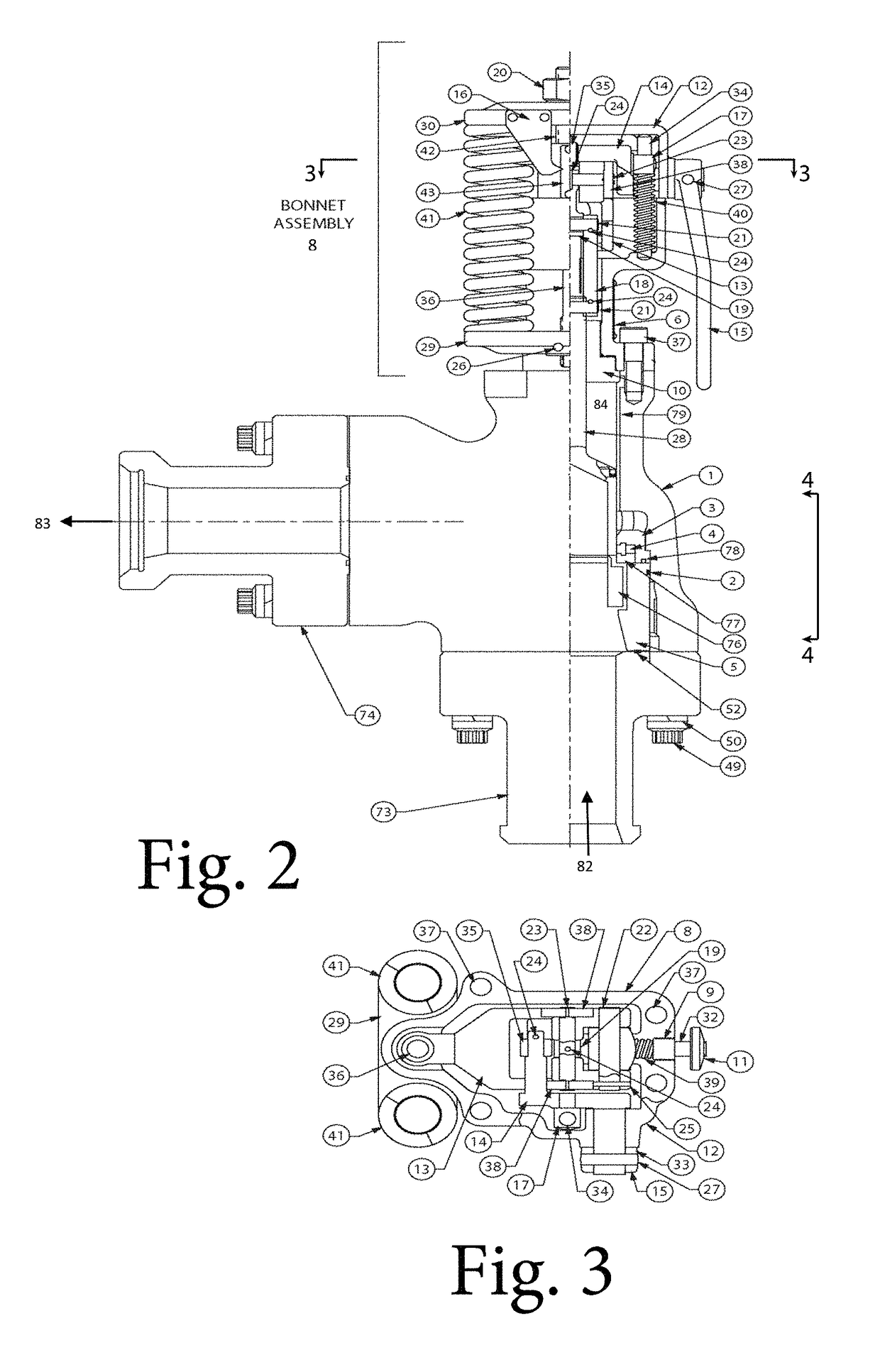
[0028]In one or more embodiments, a pressure relief valve 1000, shown in FIGS. 1-17, has a body 1, a piston 28, shown in detail in FIGS. 15A-15C, movably disposed within the body 1, and a bonnet assembly 8. In one or more embodiments, the pressure relief valve is typically connected to a line conduit (e.g. a pipe) in fluid communication with a fluid system c...


PUM


Abstract

An inlet port provides a fluid entrance to a body. A chamber has an inner surface. An outlet port is in fluid communication with the chamber and provides a fluid exit from the body. The piston is moveable within the chamber between a first set position, in which the inlet port is not in fluid communication with the outlet port, and a second open position, in which the inlet port is in fluid communication with the outlet port through the chamber. A seal guard is slidably disposed within the chamber. The seal guard is moveable between a first seal-guard position and a second seal-guard position in which the seal guard shields the seal. The seal guard is in the first seal-guard position when the piston is in its first set position and in the second seal-guard position when the piston is in its second open position.

Description

CROSS-REFERENCE TO RELATED APPLICATIONS[0001]This application is a continuation of U.S. application Ser. No. 14 / 291,301, filed on May 30, 2014, entitled “Pressure Relief Valve,”, which is incorporated by reference in its entirety. This application claims the benefit of U.S. Provisional Application No. 61 / 829,724, filed on May 31, 2013, entitled “Pressure Relief Valve,”, which is incorporated by reference in its entirety.BACKGROUND[0002]This invention relates generally to pressure relief valves and more specifically to a quick-opening, or pop-off type, reset relief valves.[0003]Pressure relief valves are important components in certain fluid flow systems in which undesirable high pressure may occur. In such systems, overpressure can damage valuable processing equipment, cause rupture of weak components, and / or a breakdown of the system. In many applications, it is desirable that when a pre-designated or pre-determined threshold pressure is exceeded, the pressure relief valve opens ve...

Claims


Application Information

Patent Timeline
Patent Type & Authority Patents(United States)
IPC IPC(8): F16K17/04F16K17/08F16K3/02F16J15/3204F16J9/12F16J15/56
CPCF16K17/0426F16K17/082F16J15/3204F16K3/0263F16K17/0466F16J15/56F16J9/12F16K25/005F16K17/06F16K3/18
Inventor LATTIMER, DANIEL GREENFIELD
Owner MARATHON VALVE LLC
Learn More