
Piezoelectric vibration component having distinguishable opposing principal surfaces

a technology of opposing principal surfaces and components, applied in the direction of piezoelectric/electrostrictive/magnetostrictive devices, electrical apparatus, impedence networks, etc., can solve the problems of difficult to determine whether or not cr films are present, difficult to determine that mounting failure has occurred, and risk of reducing bonding strength, etc., to achieve sufficient bonding strength

Active Publication Date: 2017-08-08
MURATA MFG CO LTD
View PDF17 Cites 0 Cited by
  • Summary
  • Abstract
  • Description
  • Claims
  • Application Information

AI Technical Summary

Benefits of technology

The present invention provides a piezoelectric vibration component with a strong bonding electrode and easy identification of the top and bottom surfaces. The electrodes can have different shapes, which simplifies the process and reduces costs. The component allows for reliable identification of the top and bottom surfaces, even when frequency adjustment is performed using an ion beam. Overall, the invention provides a piezoelectric vibration component with high bonding strength that is easy to produce and modify.

Problems solved by technology

Therefore, it is difficult to determine whether or not the Cr films are present.
Accordingly, when the piezoelectric vibrator is mounted on a package substrate with a back surface, to which a conductive bonding material is to be applied, racing upward by mistake, it difficult to determine that a mounting failure has occurred.
If the piezoelectric vibrator is mounted on the package substrate such that a surface having a low bondability to the conductive bonding material faces the package substrate by mistake, there is a risk that the bonding strength will be reduced.
When the piezoelectric vibrator is mounted in the inverted orientation by mistake as described above, in particular, when the outermost layer is a Cr film or the like that has a high bonding strength with respect to the conductive adhesive, there is a risk that the frequency adjustment using the ion beam will become difficult.
Therefore, there is a problem that high production costs are incurred.

Method used


Image

  • Piezoelectric vibration component having distinguishable opposing principal surfaces
  • Piezoelectric vibration component having distinguishable opposing principal surfaces
  • Piezoelectric vibration component having distinguishable opposing principal surfaces

Examples


first embodiment

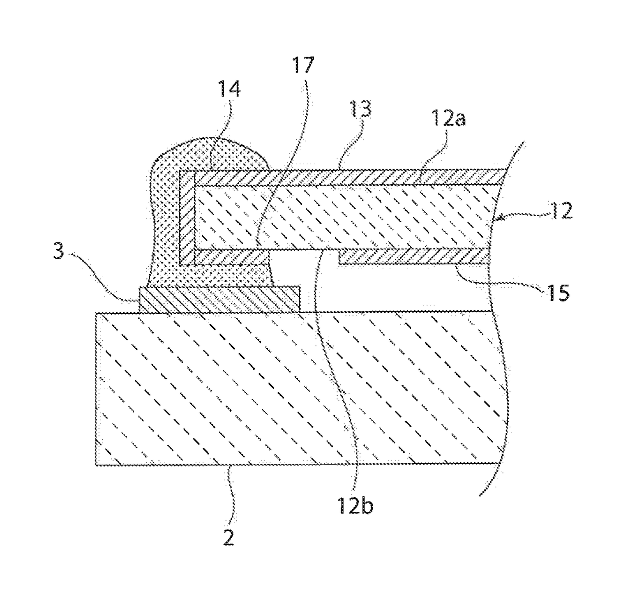
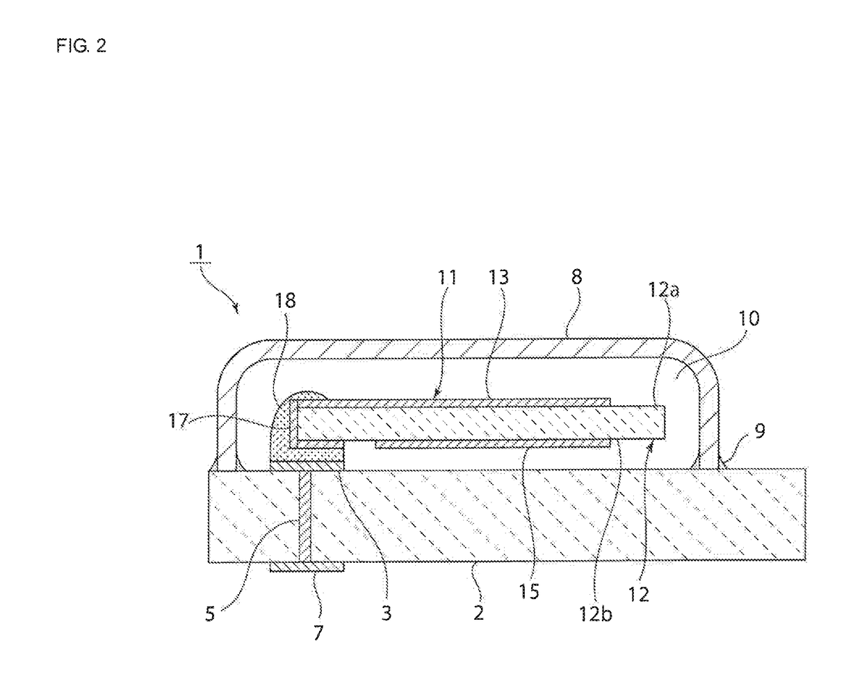
[0030]FIG. 2 is a front sectional view of a piezoelectric vibration component according to the present invention.

[0031]A piezoelectric vibration component 1 includes a package substrate 2 that serves as a first package member. In the present embodiment, the package substrate 2 is formed of a single insulating ceramic layer. The package substrate 2 may instead be formed of a monolithic ceramic substrate obtained by stacking a plurality of ceramic layers.

[0032]As illustrated in FIG. 3, connection electrodes 3 and 4 are formed on the top surface of the package substrate 2. The connection electrodes 3 and 4 are connected to top ends of via-hole electrodes 5 and 6, which are shown by the dashed lines in FIG. 3.

[0033]As illustrated in FIG. 2, the other end of the via-hole electrode 5 extends to the bottom surface of the package substrate 2, and an external electrode 7 is formed, on the bottom surface of the package substrate 2. Although not illustrated, the bottom end of the via-hole elec...

second embodiment

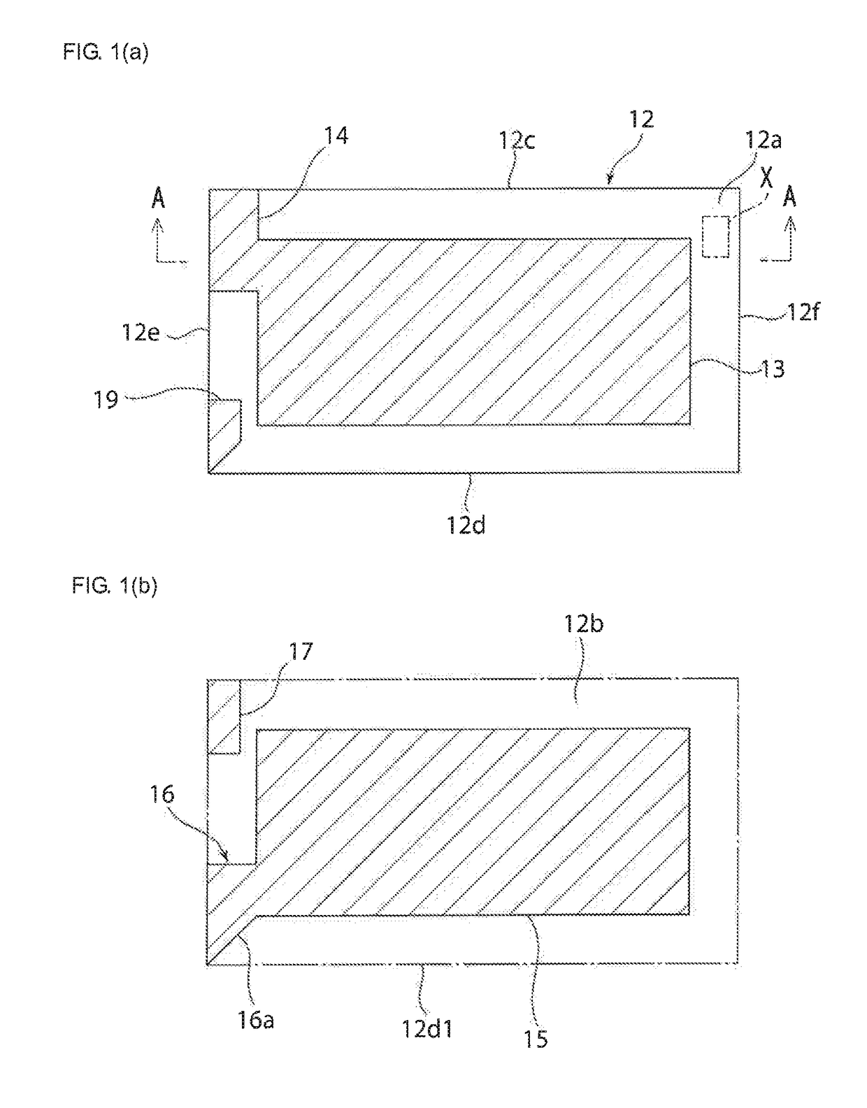
[0062]FIGS. 5(a) and 5(b) are schematic plan views illustrating electrode structures on a first principal surface and a second principal surface of a piezoelectric substrate included in a piezoelectric vibration component according to the present invention.

[0063]As illustrated in FIG. 5(a), on a first principal surface 12a, a first extended electrode 14 that extends continuously from a first vibration electrode 13 is located at a corner section formed by a long side 12c and the short side 12e. The first extended electrode 14 extend along both the long side 12c and the snort side 12e at the corner section. A second extended electrode 16 formed on a second principal surface 12b includes sides 16a and 15a that extend at an angle in a similar manner. The area of an electrode portion between the sides 16a and 16a is smaller than the area of an electrode portion between sides 14a and 14b of the first extended electrode 14. The first extended electrode 14 is electrically connected to an el...


PUM


Abstract

A piezoelectric vibration component that includes a sealed space formed between first and second package members, and a piezoelectric vibrator is bonded to the first package member with first and second conductive adhesive portions. In the piezoelectric vibrator, a first vibration electrode and a first extended electrode are formed on a first surface of a piezoelectric substrate, and a second vibration electrode and a second extended electrode are formed on a second surface of the piezoelectric substrate. At least the second extended electrode provided on the second principal surface has a higher bonding strength with respect to the conductive adhesive than that of the electrodes on the first principal surface. The electrode patterns on the first and second principal surfaces differ from each other so that the first surface and the second surface can be distinguished from each other.

Description

CROSS REFERENCE TO RELATED APPLICATIONS[0001]The present application is a continuation of PCT / JP2013 / 067472 filed Jun. 26, 2013, which claims priority to Japanese Patent Application No. 2012-212778, filed Sep. 26, 2012, the entire contents of each of which are incorporated herein by reference.FIELD OF THE INVENTION[0002]The present invention relates to piezoelectric vibration components in which a piezoelectric vibrator is disposed in an inner sealed space formed between first and second package members. In particular, the present invention relates to a piezoelectric vibration component in which a piezoelectric vibrator is bonded to a package member with a conductive adhesive portion.BACKGROUND OF THE INVENTION[0003]Various types of piezoelectric vibration components in which a piezoelectric vibrator is disposed in a sealed space of a package have been proposed.[0004]For example, Patent Document 1 listed below discloses a crystal vibration device in which a quartz oscillator is disp...

Claims


Application Information

Patent Timeline
Patent Type & Authority Patents(United States)
IPC IPC(8): H01L41/053H03H9/10H01L41/047H03H9/05H03H9/17H03H9/19H03H9/13
CPCH03H9/1021H01L41/0475H01L41/053H03H9/0519H03H9/17H03H9/131H10N30/88H10N30/875
Inventor OKAMOTO, BUNTAOISHIBASHI, HIDEKAZU
Owner MURATA MFG CO LTD
Learn More