
Light source device and display apparatus

a light source and display device technology, applied in the direction of instruments, optical light guides, optics, etc., can solve the problems of damage to the light source, difficulty in providing the regulating part, etc., and achieve the effect of improving display quality and maintaining stability

Active Publication Date: 2017-07-25
SAKAI DISPLAY PROD
View PDF6 Cites 0 Cited by
  • Summary
  • Abstract
  • Description
  • Claims
  • Application Information

AI Technical Summary

Benefits of technology

[0009]The present invention has been made with the aim of solving the above problems. It is an object of the present invention to provide a light source device which is capable of miniaturizing and appropriately maintaining a position of a light guide plate with respect to a light source unit, and a display apparatus including the light source device.
[0024]According to the present invention, in the light source device in which the light source units are disposed to face the two opposite end surfaces of the light guide plate, the light guide plate is pinched through the other two end surfaces, such that it is possible to constantly maintain a distance between the light guide plate and the respective light source units, and uniformly emit the light. In addition, the pinching units for pinching the light guide plate are provided on the other two end surface sides, such that the configuration of the two end surface sides in which the light source units are disposed can be simplified, and the light source device can be miniaturized. Thereby, even when the size of the light source device is limited, it is possible to appropriately maintain the position of the light guide plate.

Problems solved by technology

However, as the display apparatus is thinned and narrowed, thinning and miniaturizing of the light source unit are required, and thus it is difficult to provide the regulating part as disclosed in International Publication No. 2011 / 093136 in the substrate holding member.
When such the heat expansion and position shift of the light guide plate due to its own weight have simultaneously occurred, the light guide plate may contact the light source to damage the light source.

Method used


Image

  • Light source device and display apparatus
  • Light source device and display apparatus
  • Light source device and display apparatus

Examples


embodiment 1

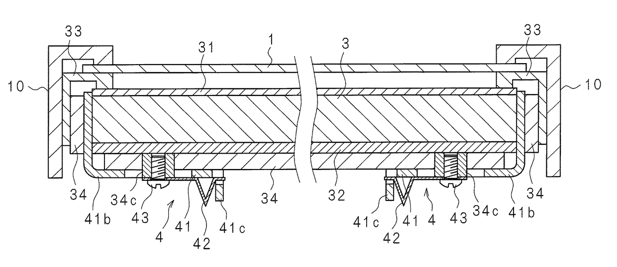
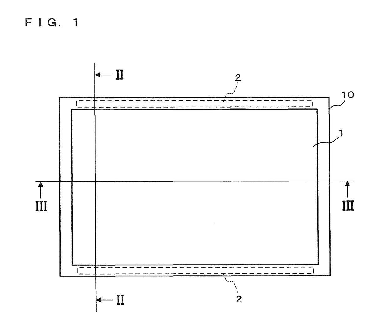
[0037]FIG. 1 is a front view of a display apparatus according to Embodiment 1, FIG. 2 is a longitudinal cross-sectional view taken on line II-II in FIG. 1, FIG. 3 is a transverse cross-sectional view taken on line III-III in FIG. 1, and FIG. 4 is an exploded perspective view illustrating a configuration of major components of the display apparatus according to Embodiment 1. The display apparatus of Embodiment 1 is a liquid crystal display apparatus including an edge light type light source device. The display apparatus of Embodiment 1 includes a rectangular plate-shaped liquid crystal panel (display panel) 1, and the light source device which irradiates the liquid crystal panel 1 with light.

[0038]The liquid crystal panel 1 is formed by arranging a plurality of liquid crystal elements in a two-dimensional matrix shape, for example. Peripheral edges of the liquid crystal panel 1 are covered by a bezel 10 from a display screen side. The light source device includes two light source uni...

embodiment 2

[0063]Hereinafter, a display apparatus according to Embodiment 2 will be described. The display apparatus of Embodiment 2 is different from the above-described display apparatus of Embodiment 1 in terms of the configuration of a pinching member 4 attached to the rear cover 34. Accordingly, only the pinching member 4 will be described, and the components having configurations common to Embodiment 1 are denoted by the same reference numerals and will not be described.

[0064]FIG. 7 is a transverse cross-sectional view taken on line III-III in FIG. 1, FIG. 8 is an exploded perspective view illustrating a configuration of main components of the display apparatus according to Embodiment 2, and FIGS. 9 and 10 are explanatory views illustrating an attaching procedure of the pinching member 4 of Embodiment 2.

[0065]The pinching member 4 of Embodiment 2 includes a washer 44 and a curved leaf spring 45 instead of the leaf spring 42 in Embodiment 1.

[0066]The curved leaf spring 45 is formed by ben...


PUM

PropertyMeasurementUnit
thicknessaaaaaaaaaa
distanceaaaaaaaaaa
sizeaaaaaaaaaa

Abstract

Light sources are disposed to face two opposite end surfaces of light guide plate. Cutout parts are provided at respective centers of other two opposite end surfaces of the light guide plate. Pinching members which pinch the light guide plate are attached to rear cover which covers one surface of the light guide plate, the pinching members being at positions corresponding to the respective cutout parts of the light guide plate. The rear cover pinches the other two opposite end surfaces of the light guide plate by two pinching members, while supporting the one surface of the light guide plate.

Description

CROSS-REFERENCE TO RELATED APPLICATION[0001]This application is the national phase under 35 U.S.C. §371 of PCT International Application No. PCT / JP2014 / 065899 which has an International filing date of Jun. 16, 2014 and designated the United States of America.BACKGROUND[0002]1. Technical Field[0003]The present invention relates to an edge light type light source device, and a display apparatus including the light source device.[0004]2. Description of Related Art[0005]Recently, a display apparatus such as a liquid crystal display and a liquid crystal television has been widely spread. Such the display apparatus includes: a rectangular plate-shaped display panel which has a display screen displaying an image on a front side; and a light source unit which is disposed on a rear side of the display panel to emit light to the display panel. There is an edge light type light source unit in which a light guide plate and a support member for supporting the light guide plate are disposed on th...

Claims


Application Information

Patent Timeline
Patent Type & Authority Patents(United States)
IPC IPC(8): F21V8/00G02F1/1335G02F1/1333
CPCG02B6/0088G02B6/0091G02F1/133308G02F1/133608G02F2001/133314G02F1/133314
Inventor SASAKI, TOMOO
Owner SAKAI DISPLAY PROD
Learn More