
Light converging member and optical component

Pending Publication Date: 2022-09-22
NGK INSULATORS LTD
View PDF0 Cites 0 Cited by
  • Summary
  • Abstract
  • Description
  • Claims
  • Application Information

AI Technical Summary

Benefits of technology

The present invention provides a light converging member and an optical component that can achieve both reduction in light distribution angle and miniaturization of a light source. This means that the invention can reduce the size of a light source while also controlling the spread of light.

Problems solved by technology

However, in order to obtain a narrow light distribution angle in a surface emitting light source such as an LED, a large lens is generally used, and it is not easy to achieve both reduction in the light distribution angle (narrowing of the angle) and miniaturization of the light source.

Method used


Image

  • Light converging member and optical component
  • Light converging member and optical component
  • Light converging member and optical component

Examples


example

[0045]The light distribution angle θf was confirmed for Examples 1 to 18 and Comparative Examples 1 to 5. In some examples, a light extraction efficiency E and the illuminance I were also confirmed.

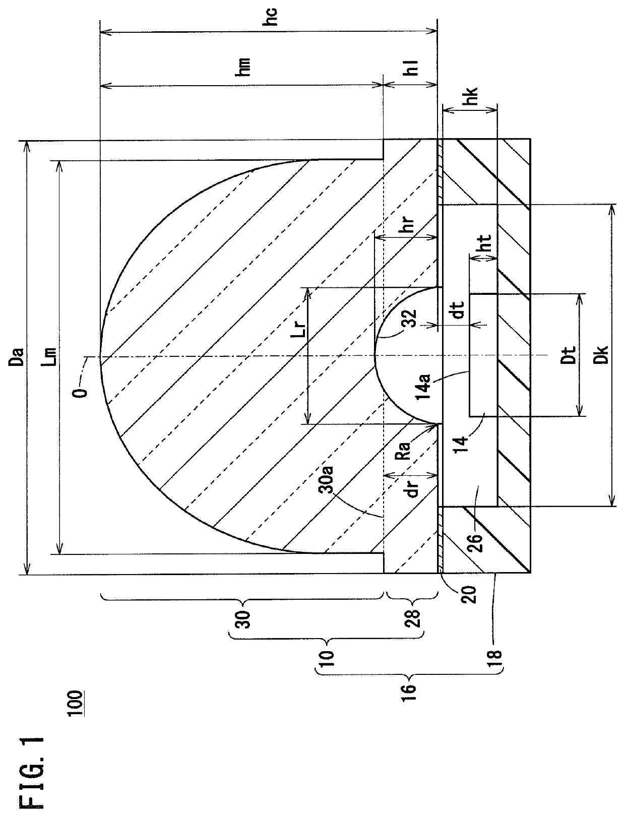
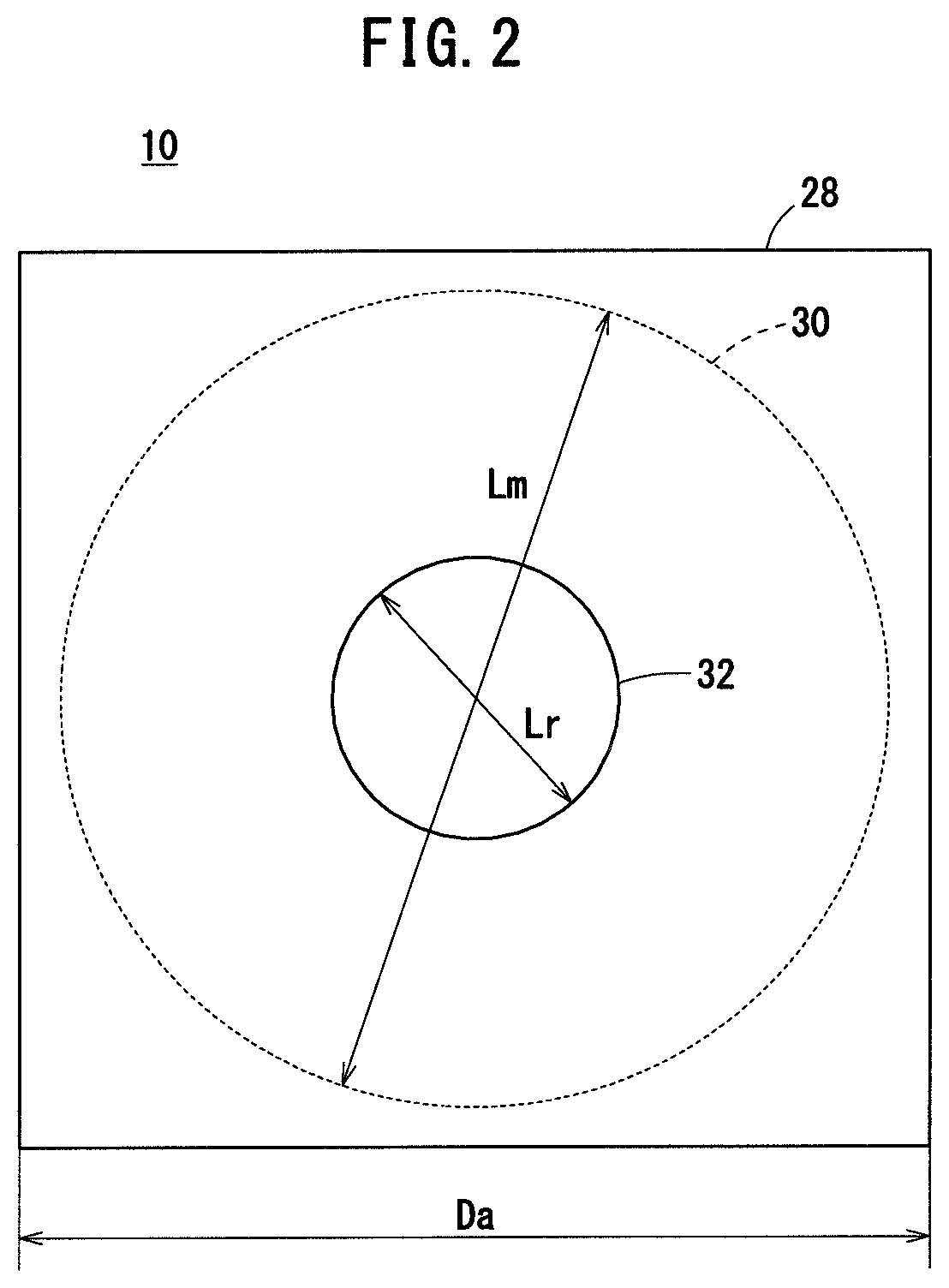
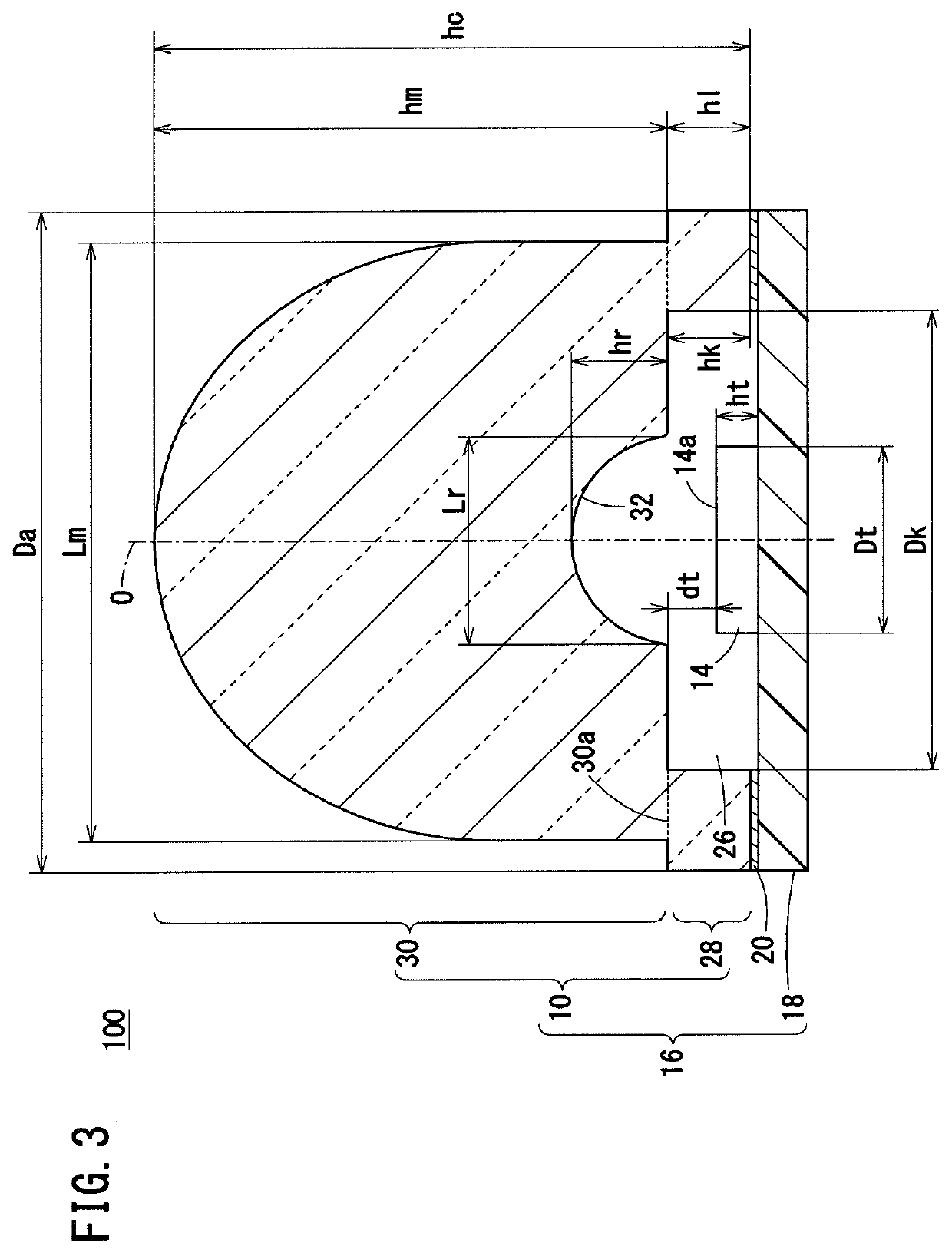
[0046]The examples and the comparative examples can be basically represented by FIG. 1. In these examples and comparative examples, the shape, the diameter Lr, and the depth hr of the concave portion 32 were changed as follows (see Table 1).

[0047]The shape of the concave portion 32 was a hemispherical dome shape in Examples 1 to 11 and Comparative Examples 2 to 4, a low dome shape in Examples 12 and 13, a tall dome shape in Examples 14 to 17 and Comparative Example 5, and a columnar shape in Example 18. In Comparative Example 1, the concave portion 32 was not provided.

[0048]The aspect ratio Rr (hr / Lr) is 0.5 for the hemispherical dome shape, is less than 0.5 for the low dome shape, and is greater than 0.5 for the tall dome shape.

[0049]The diameters Lr in Comparative Examples 2 to 4 and Ex...


PUM


Abstract

A light converging member (10) according to an embodiment of the present invention includes: a recess portion (32) that is used for an optical component (100) with an optical element (14) for emitting light, the recess portion being opposed to the optical element (14) and having a size 0.5 or more times larger than the maximum length of a light emission region in the optical element; and a lens body (30) for converging light having passed through the recess portion (32).

Description

CROSS-REFERENCE TO RELATED APPLICATIONS[0001]This application is a Continuation of International Application No. PCT / JP2020 / 044428 filed on Nov. 30, 2020, which is based upon and claims the benefit of priority from Japanese Patent Application No. 2019-222658 filed on Dec. 10, 2019, the contents all of which are incorporated herein by reference.TECHNICAL FIELD[0002]The present invention relates to a light converging member that converges light from an optical element, and to an optical component.BACKGROUND ART[0003]Ultraviolet light sources are used in various fields such as purification, sterilization, and optical analysis. As the ultraviolet light source, an optical element (for example, LED: light emitting diode, LD: semiconductor laser) which can be easily miniaturized has been developed (see JP 2016-121926 A).[0004]Here, for example, for optical analysis (as an example, concentration analysis of deoxyribonucleic acid (DNA)), it is preferable that a change in intensity of light d...

Claims


Application Information

Patent Timeline
IPC IPC(8): F21V5/04
CPCF21V5/04F21Y2115/10F21Y2115/30G02B3/04H01L33/58
Inventor KIKUCHI, YOSHIO
Owner NGK INSULATORS LTD
Learn More