
Light source system

a light source and light beam technology, applied in free standing, lighting and heating equipment, instruments, etc., can solve the problem of further miniaturization of the light source system, and achieve the effect of preventing premature failure of the bulb and preventing long-term exposure of reflected light beams

Inactive Publication Date: 2013-04-11
DELTA ELECTRONICS INC
View PDF2 Cites 0 Cited by
  • Summary
  • Abstract
  • Description
  • Claims
  • Application Information

AI Technical Summary

Benefits of technology

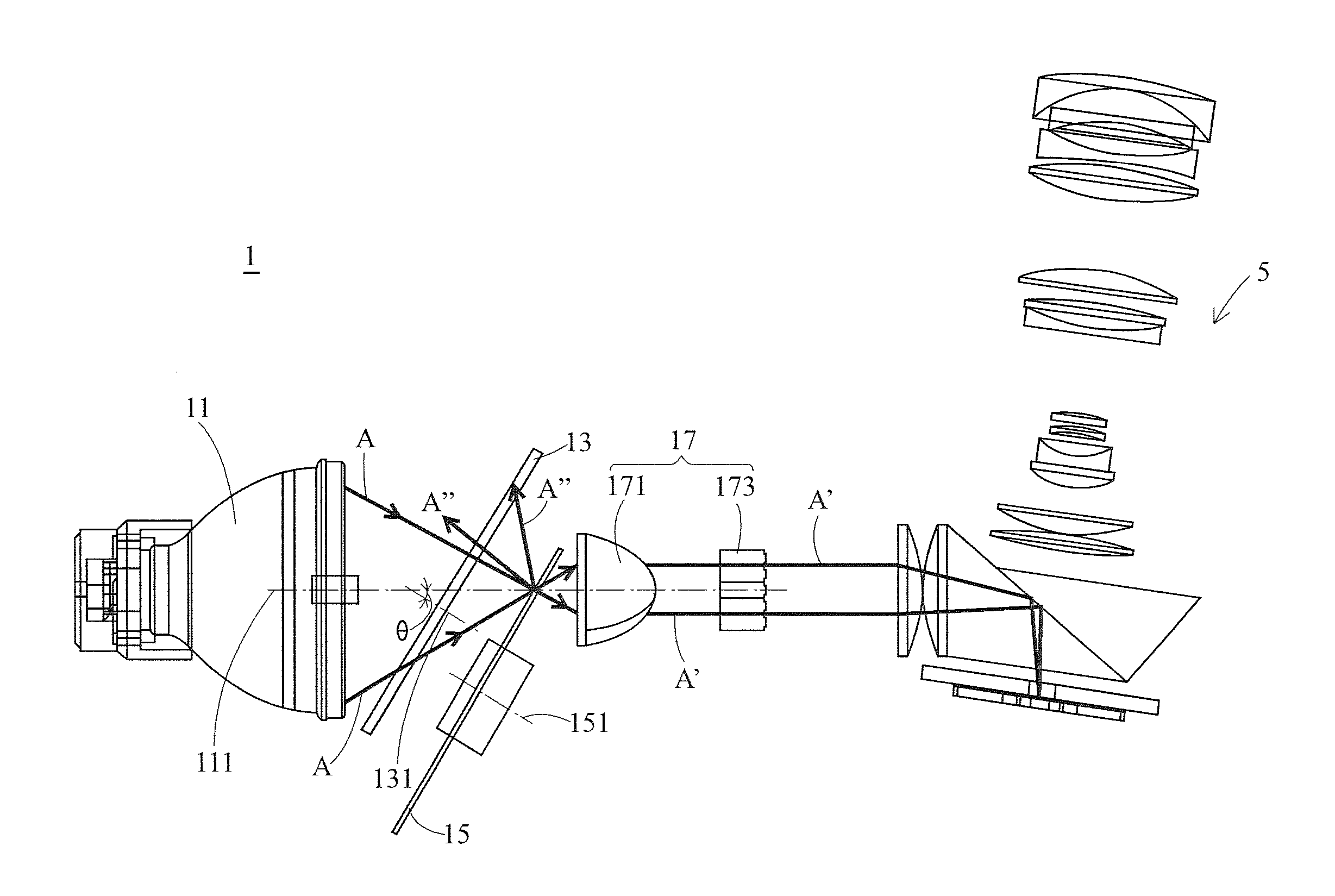
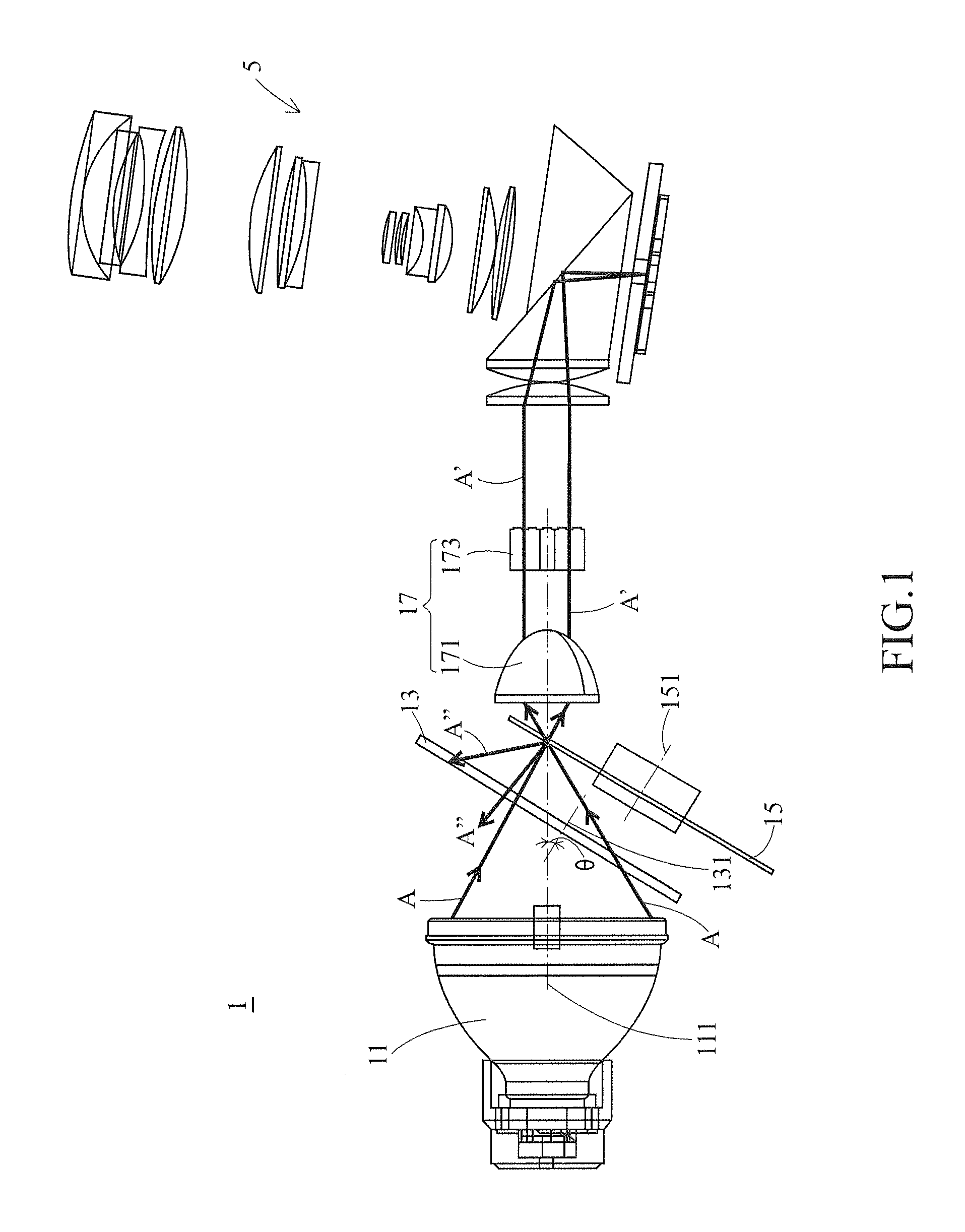
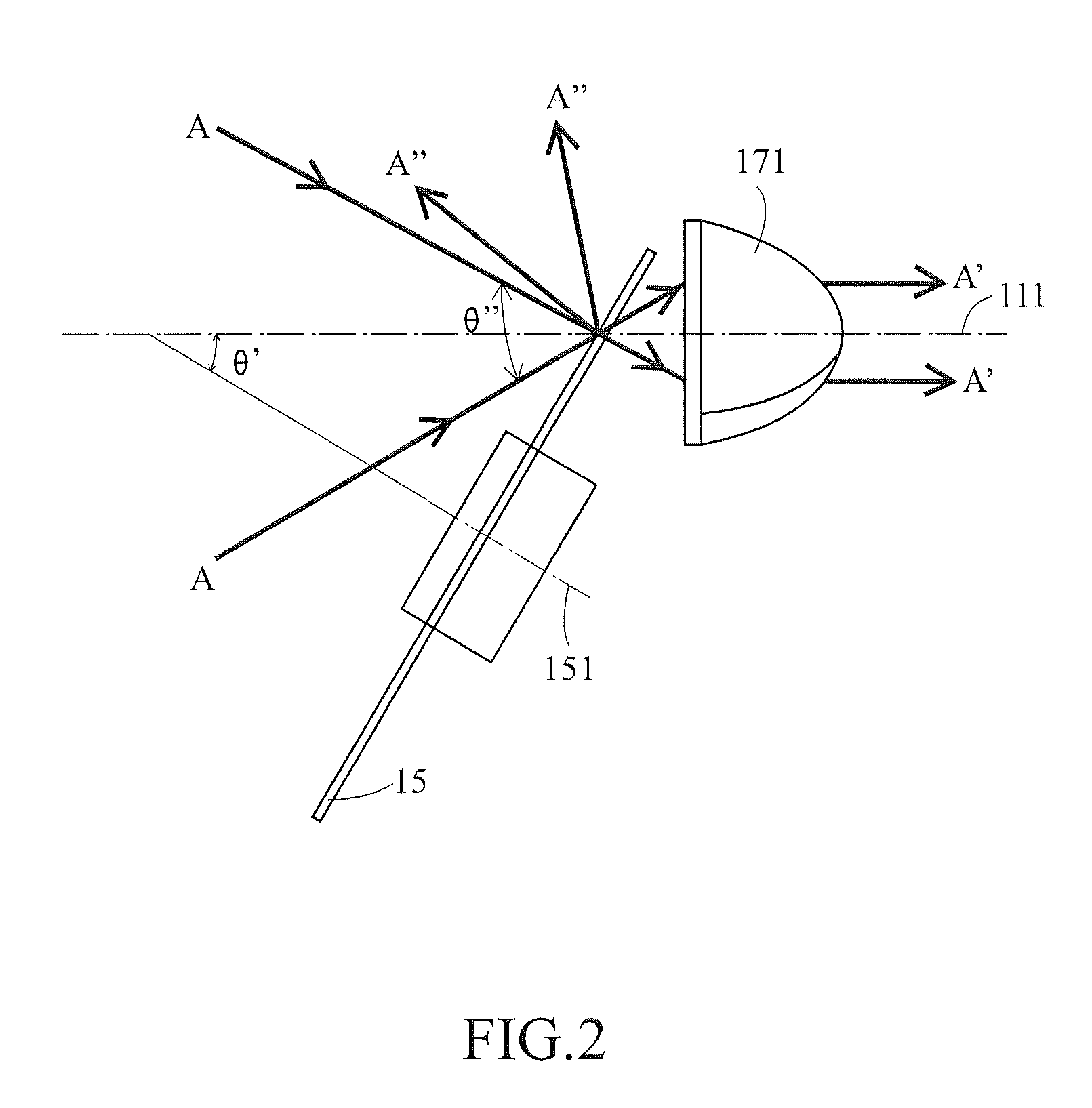
The present invention provides a light source system that prevents long-term exposure of reflected light beams to a bulb, which can prematurely fail it. This is achieved by deflecting a color wheel with an angle, so that the reflected light beams are directed away from the bulb. Additionally, a fly eyes lens is used to further uniformize the light beams and make them travel along a predetermined optical axis, which reduces the size of the light source system.

Problems solved by technology

This can further miniaturize the light source system.

Method used


Image

  • Light source system
  • Light source system
  • Light source system

Examples


Embodiment Construction

[0017]In the following descriptions, the present invention will be explained with reference to embodiments thereof The present invention relates to a light source system. It shall be appreciated that in the following embodiments and the attached drawings, the description of these embodiments is only for the purpose of illustration rather than to limit the present invention. Meanwhile, in the following embodiments and the attached drawings, elements not directly related to the present invention are omitted from depiction; and dimensional relationships among individual elements in the attached drawings are illustrated only for ease of understanding but not to limit the actual scale.

[0018]The first embodiment of the present invention is a light source system 1 for a projection device, which is schematically shown in FIG. 1. The projection device comprises a light source system 1 and an imaging system 5. The imaging system 5 comprises, for example, a digital micromirror device, an optic...


PUM


Abstract

A light source system comprising an illumination component, a color wheel and a light uniformization module is provided. The illumination component is disposed on a first axis to provide light beams. The color wheel defines a second axis to rotate thereabout, wherein the second axis is deflected from the first axis by an angle. The light beams provided from the illumination component are substantially focused at the first axis and onto the color wheel. The light uniformization module is disposed on the first axis after the color wheel to receive a portion of the light beams and uniformize the light beams to travel along the first axis.

Description

[0001]This application claims the benefit of the priority to Taiwan Patent Application No. 100136636 filed on Oct. 11, 2011, the disclosures of which are incorporated herein by reference in their entirety.CROSS-REFERENCES TO RELATED APPLICATIONS[0002]Not applicable.BACKGROUND OF THE INVENTION[0003]1. Field of the Invention[0004]The present invention relates to a light source system for a projection device. More particularly, the present invention relates to a light source system which can prevent the premature failure of a bulb from long-term exposure to reflected light beams.[0005]2. Descriptions of the Related Art[0006]With the progress of science and technology, various display devices have been developed in succession. Among these display devices, projectors have become indispensable electronic products for presenting image information in business conferences or in common audio / video (AV) entertainments because they can change the size of an image depending on the actual service...

Claims


Application Information

Patent Timeline
IPC IPC(8): F21V13/08F21V13/04F21V7/00
CPCG03B21/208H04N9/3114G03B33/08
Inventor LIN, HUNG-YING
Owner DELTA ELECTRONICS INC
Learn More