
LED photo-electric source assembly and LED road lamp

a technology of led road lamps and photoelectric sources, which is applied in the direction of fixed installations, lighting and heating equipment, and roads, can solve the problems of low light efficiency, short service life, and high power consumption, and achieve the effects of reducing the working temperature of lamps, simple structure, and low cos

Inactive Publication Date: 2017-07-25
NANKER GUANGZHOU SEMICON MFG
View PDF59 Cites 6 Cited by
  • Summary
  • Abstract
  • Description
  • Claims
  • Application Information

AI Technical Summary

Benefits of technology

The solution provides effective heat dissipation, improved stability and service life, while maintaining a simple structure and ensuring waterproof and dustproof characteristics, reducing maintenance costs and avoiding repeated investments.

Problems solved by technology

The traditional road lamp is usually made with a halogen lamp, such as a sodium lamp, which have high power consumption, short service life and low light efficiency.
In considering heat dissipation, their radiators are exposed, and the traditional lamp is so small due to LEDs own small volume, thereby current road lamps' shape are strange and monotonous.
So this will cause repeated investment and waste.
It will be much trouble to maintain with low efficiency and high cost.
Heat dissipation has become a technological difficulty for wide application of the device.
So when one needs to improve heat dissipation effects, it is necessary to increase heat dissipation area as much as possible, but this will cause the size of a current LED lamp to become bigger and make the structure more complicated.
Also, the heat dissipation effect is unsatisfied.
But in exchange for improving the heat dissipation effect on a high power road lamp, the resulting open structure has poor waterproofing and dustproofing characteristics.
Also it may be necessary to design a much more complicated ventilation structure for increasing heat dissipation.
Both are unsatisfactory due to low heat conductivity coefficients.
Also, thermally conductive silicone is made of an unstable paste so it is difficult to spread evenly between the light source board and radiator.
This will cause poor thermal conductivity and reduce insulating properties, thereby causing a short circuit.
Thermally conductive empire cloth is easy to transform, and can also be troublesome to install and less efficient.

Method used


Image

  • LED photo-electric source assembly and LED road lamp
  • LED photo-electric source assembly and LED road lamp
  • LED photo-electric source assembly and LED road lamp

Examples


embodiment i

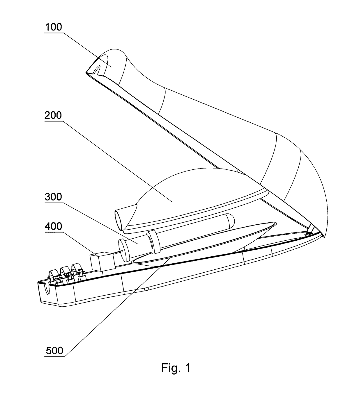
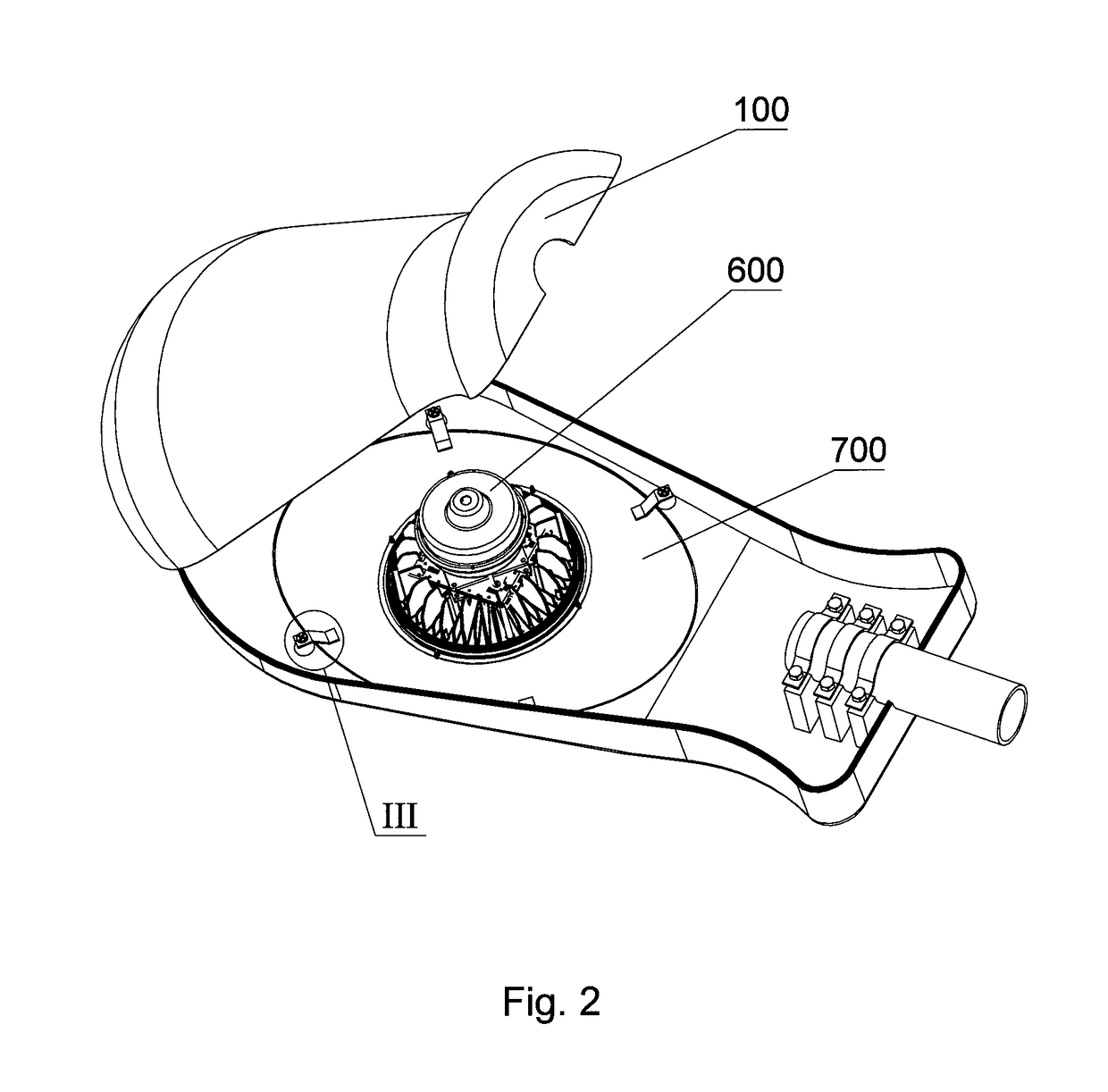
[0044]With reference to FIG. 2, FIG. 3 and FIG. 7-FIG. 14, an LED road lamp comprises an LED photo-electric source assembly 600, an installing board 700, and a housing assembly 100 of a traditional road lamp for containing light source, wherein a light outlet 701 arranged on the installing board 700 adapts in size and shape to an opening arranged at the bottom of the housing assembly 100; in this embodiment the installing board 700 is oval, and the light outlet 701 is circular; the LED photo-electric source assembly 600 is fixedly connected to the installing board 700 and emits light through the light outlet 701 and the installing board 700 is fixedly connected with the housing assembly 100 through a clamping fixture; the detailed connecting method as: four installing holes 702 is on the installing board 700 around the light outlet 701; one or more install bolts 98 are fixedly connected to the installing board 700 through the installing holes 702 by a nut 99, afterwards the installi...

embodiment ii

[0047]As shown in FIG. 4 and FIGS. 15-20, an embodiment of LED road lamp improved from traditional road lamp is different from embodiment I is provided as: this embodiment has removed decorate circle 6; also, the LED photo-electric source assembly components 600 further comprise a wind scooper 10 with a flared shape; the wind scooper 10 is fixedly connected to the radiator 1 by one or more connecting bolts 98 across the top edge of the wind scooper 10, which surrounds the side of the radiating part 12; an annular air outlet 61 between bottom of the wind scooper 10 with bottom of the radiator 1 is provided; the outside air flows into the radiating fan 2 from the space between the lower cover 32 with the radiator 1, and flows outside through the annular air outlet 61 after passing through the channel inside of the radiating part 12; the bottom of the wind scooper 10 has an outer edge arranged, to hold down the installing board 700 and is fixedly connected by bolts, and adapts in size ...

embodiment iii

[0052]As shown in FIG. 5, this embodiment of the LED road lamp improved from traditional road lamp is different from embodiment I as: several ventilation slots 703 as a heat part in the installing board 700 are provided. Further, an installation hole for the fan is in the installing board 700, and an outer radiating fan 800 is on the installation hole. In this way, inner air and outside air circulation of the housing assembly 100 is improved.

[0053]Other characters in this embodiment are the same as Embodiment I.


PUM


Abstract

An LED photo-electric source assembly includes a radiator, a radiating fan, a driving circuit board subassembly, an LED light source component, an upper cover of a power supply box, a lower cover of the power supply box and a waterproof bolt component. The radiator comprises a bottom plate, on top of which a radiating part is provided. A space area of the radiating part contains a dust-proof, water-proof fan. An LED road lamp further includes an LED photo-electric source assembly, an installing board and a housing assembly of a traditional road lamp for containing light source. A light outlet arranged on the installing board adapts in size and shape to an opening arranged at the bottom of the housing assembly. The LED photo-electric source assembly is fixedly connected to the installing board and emits light. The installing board is fixedly connected with the housing assembly through a clamping fixture.

Description

CROSS-REFERENCE TO RELATED PATENT APPLICATIONS[0001]This application is a U.S. National Phase Application under 35 U.S.C. §371 of International Patent Application No. PCT / CN2012 / 079863 filed on Aug. 9, 2012, and claims the benefit of Chinese Patent Application No. 201110303619.6 filed on Oct. 2, 2011 and No. 201110416430.8 filed on Dec. 13, 2011, the entire contents of which are incorporated by reference as if set forth in their entirely herein. The International Application was published on Apr. 11, 2013 as International Publication No. WO / 2013 / 049982 under PCT Article 21(2).FIELD OF THE INVENTION[0002]The present invention relates to an LED photo-electric source assembly. Also, the present invention relates to a road lamp, further to an LED road lamp improved from traditional road lamp.BACKGROUND OF THE INVENTION[0003]At present, the road lamp is a familiar lamp. The traditional road lamp is usually made with a halogen lamp, such as a sodium lamp, which have high power consumption...

Claims


Application Information

Patent Timeline
Patent Type & Authority Patents(United States)
IPC IPC(8): F21S8/00F21V29/67F21V23/02F21V23/00F21V31/00F21V19/00F21V5/04F21V5/00F21V17/12F21V29/77F21W111/02F21W131/103F21Y105/10F21Y115/10
CPCF21V29/67F21S8/00F21V19/0055F21V23/009F21V23/023F21V29/673F21V31/00F21V31/005F21V5/007F21V5/04F21V17/12F21V29/773F21W2111/02F21W2131/103F21Y2105/10F21Y2115/10Y02B20/72
Inventor WU, CHUN-WEI
Owner NANKER GUANGZHOU SEMICON MFG
Learn More