
In-building-communication apparatus and method

a communication apparatus and in-building technology, applied in the field of in-building communication apparatus and method, can solve the problems of increasing man-made interference in the 800 mhz band, increasing the difficulty of ensuring quality reception, and reducing the energy to carry the same amount, so as to overcome the physical barriers to radio wave transmission quickly and safely in an in-building communication application. , the effect of reducing the path loss of radio waves

Active Publication Date: 2017-07-18
SCHEUCHER KARL FREDERICK
View PDF128 Cites 30 Cited by
  • Summary
  • Abstract
  • Description
  • Claims
  • Application Information

AI Technical Summary

Benefits of technology

The SIPS-BDA system effectively eliminates communication dead zones in buildings by enhancing signal strength and reducing interference, enabling rapid and reliable communication between emergency responders without the need for extensive infrastructure or power connections, thus ensuring effective communication during emergencies.

Problems solved by technology

As the bandwidth has become more crowded, there is increasing difficulty to ensure quality reception.
The reduced bandwidth means reduced energy to carry the same amount of information over the same distance increasing the challenge of reliable communications.
However, the large number of cellular phone company and other spectrum users has led to increasing man-made interference in the 800 MHz band.
Variations in the signal level at the receiver may be due to manmade sources or natural structures including multipath interference, internal noise in the electronic circuit, structures blocking or obstructing pathway of the radio waves, natural noise, near-far interference, intermodulation interference, receiver desensitization interference, or receiver overload.
While P25 was intended to serve as a common digital language for the radios and system infrastructures, system manufacturers developed proprietary features resulting in a loss of interoperability.
Further, due to difficulty of digital radios to distinguish between high background noise levels and spoken voice data has led to P25 digital portable radios not being recommended for fire-fighting applications when an SCBA facepiece is being used.
Additionally, as the radio wave travels from the transmitter to the receiver, different paths traveled by the electromagnetic waves before reaching the receiver may affect the signal quality.
Objects in the path of the radio waves such as buildings, trees, or local terrain will reduce the strength of the waves by absorbing or interrupting the signal.
Increased distance from the communications tower where the radio waves are generated can lead to weakened radio signals making it difficult for the radio waves to provide coverage inside a building.
Increasing signal strength with additional antenna sites is typically limited by the cost, spectrum availability, approval, as well as structural obstacles preventing certain building structures from receiving adequate signal necessary for In-Building Communication.
Supplemental coverage in specific buildings may add additional expense for treating each building separately and these individual systems may create problematic interference.
Most importantly, permanent building specific solutions may not be reliable during an actual event at the building location.
For example, a building fire may damage these systems or the antenna or power lines essential for communications.
Bi-directional amplifier communications systems are subject to oscillation when there is inadequate isolation (path loss) between the transmitting and receiving antenna.
Because this type of oscillation can lead to serious interference disrupting other communications in the nearby area, it is illegal to operate a signal booster that oscillates and the FCC (FCC) may impose fines and confiscate equipment.

Method used


Image

  • In-building-communication apparatus and method
  • In-building-communication apparatus and method
  • In-building-communication apparatus and method

Examples


Embodiment Construction

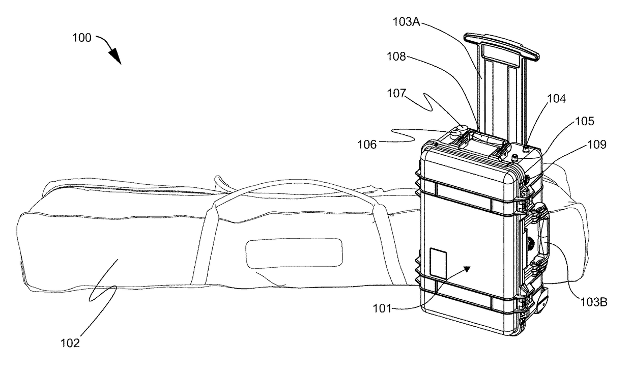
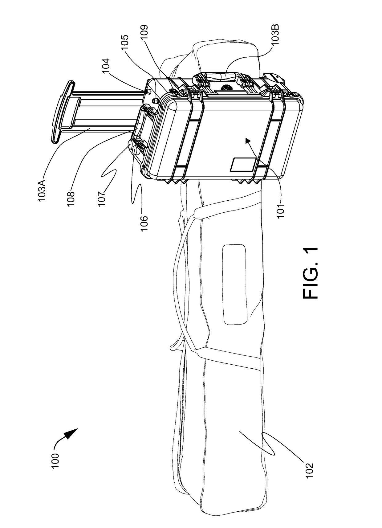
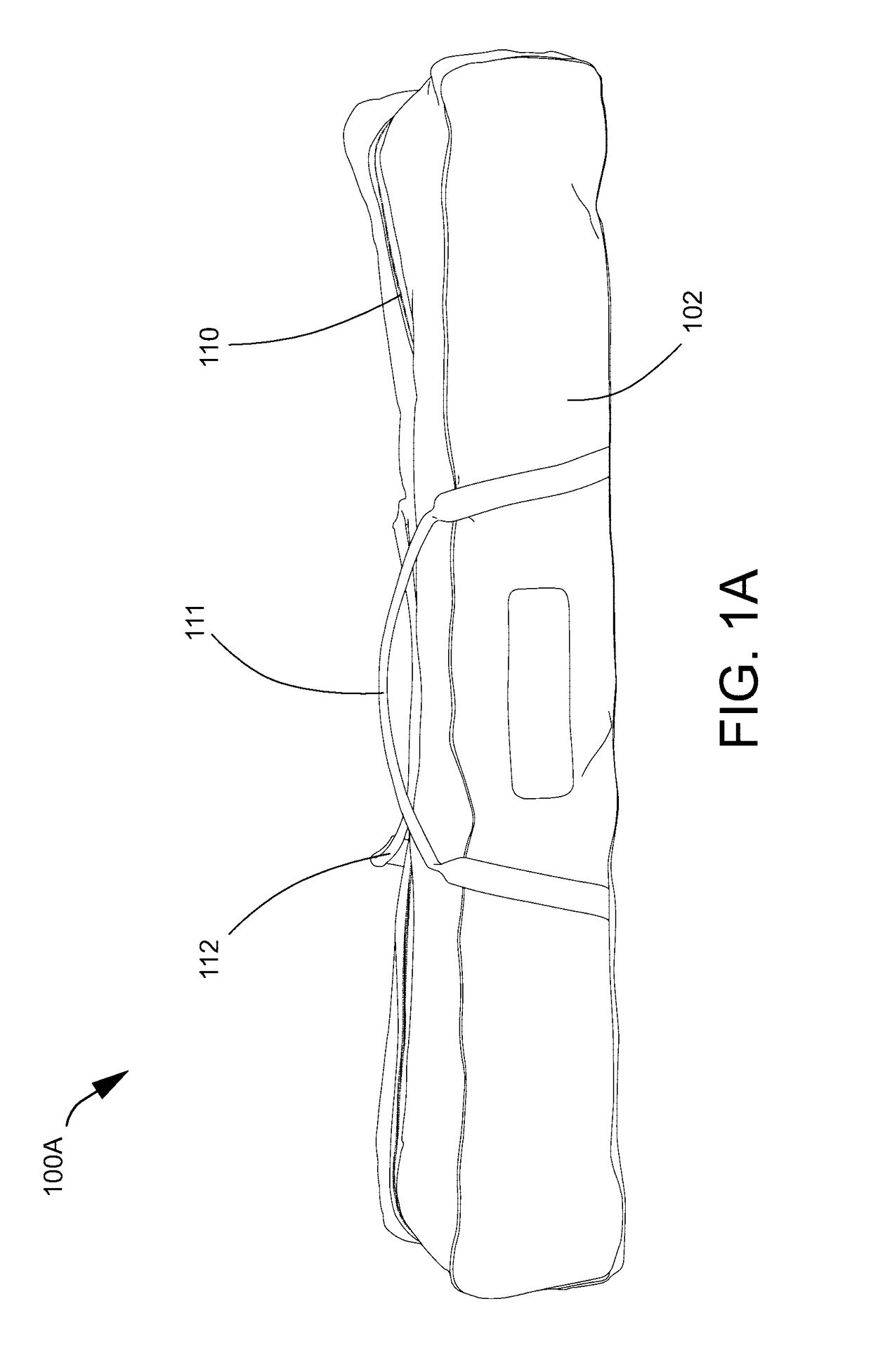
[0170]FIG. 1 is a view 100 of in-building communication system including a portable amplifier kit 101 and a portable antenna kit 102. The portable amplifier kit 101 has a rectangular shape and stands in an upright lengthwise direction. The longest side of the amplifier kit is perpendicular to the ground. The top portion of the portable amplifier kit when standing in an upright lengthwise position includes a sliding handle 103A, an indoor antenna connector port 104, an outdoor antenna connector port 105, a power switch 106, a status light 107, and a top handle 108. The sliding handle 103A extends past the top portion of the amplifier kit and is attached to the back panel of the amplifier kit. Power switch 106 and the status light 107 are located adjacent to each other with the power switch positioned closer to the front of the amplifier kit and the status light positioned more closely to the rear left corner on the top panel of the amplifier kit. The status light provides a large vis...


PUM


Abstract

An In-Building Communications system is disclosed which permits communication in tunnels, underground parking garages, tall buildings such as skyscrapers, buildings having thick walls of concrete or metal, and / or any building which has communication dead zones due to electromagnetic shielding. The invention includes a portable bi-directional amplifier (BDA) system, an outdoor antenna system attached to the building or independently mountable, an indoor antenna system attached to the building or independently mountable inside the building, and a standardized, In-Building Communications (IBC) interface box affixed preferably to the exterior of the building. The interface box communicates with antenna systems attached to the building. The fire department or other emergency response personnel carry portable outdoor and indoor antenna systems and a portable, lithium-ion battery powered, bi-directional amplifier (BDA) system which may be connected to the building during an event such as a fire, earthquake, or an act of terrorism or whenever radio coverage enhancement is required. The portable BDA system is simply connected to the standardized, IBC interface box and powered thus restoring communications within.

Description

[0001]This application incorporates herein by reference hereto U.S. utility patent application Ser. No. 11 / 672,853, filed Feb. 8, 2007. This application claims the benefit of the filing date of provisional application Ser. No. 61 / 148,395, filed Jan. 30, 2009 and the contents of provisional application No. 61 / 148,395 and application Ser. No. 11 / 672,853, are both expressly hereby incorporated by reference.FIELD OF THE INVENTION[0002]The invention relates to In-Building Communications (IBC) systems, distributed antenna systems (DAS), public safety communication systems, and emergency communication systems with portable, uninterruptible, hot swappable power systems.BACKGROUND OF THE INVENTION[0003]Problems with In-Building Communication are described in the Phoenix Fire Department Radio System Safety Project, Final Report, Version 1.7, dated Oct. 8, 2004, which is hereby expressly incorporated by reference and in the National Public Safety Telecommunications Council, NPSTC, Best Practic...

Claims


Application Information

Patent Timeline
Patent Type & Authority Patents(United States)
IPC IPC(8): H01Q19/30H01Q9/30
CPCH01Q19/30H01Q9/30H04B7/15557
Inventor SCHEUCHER, KARL FREDERICK
Owner SCHEUCHER KARL FREDERICK
Learn More