
Vertebral body replacement and insertion methods

a technology for vertebrae and insertion methods, applied in the field of spinal implants and implant insertion assemblies, can solve the problems of partial to total loss of bodily functions, fracturing of one or more vertebrae, and severe discomfort, and achieves the effects of reducing patient recovery time, reducing cost, and small opening

Active Publication Date: 2017-07-11
NUVASIVE
View PDF443 Cites 20 Cited by
  • Summary
  • Abstract
  • Description
  • Claims
  • Application Information

AI Technical Summary

Benefits of technology

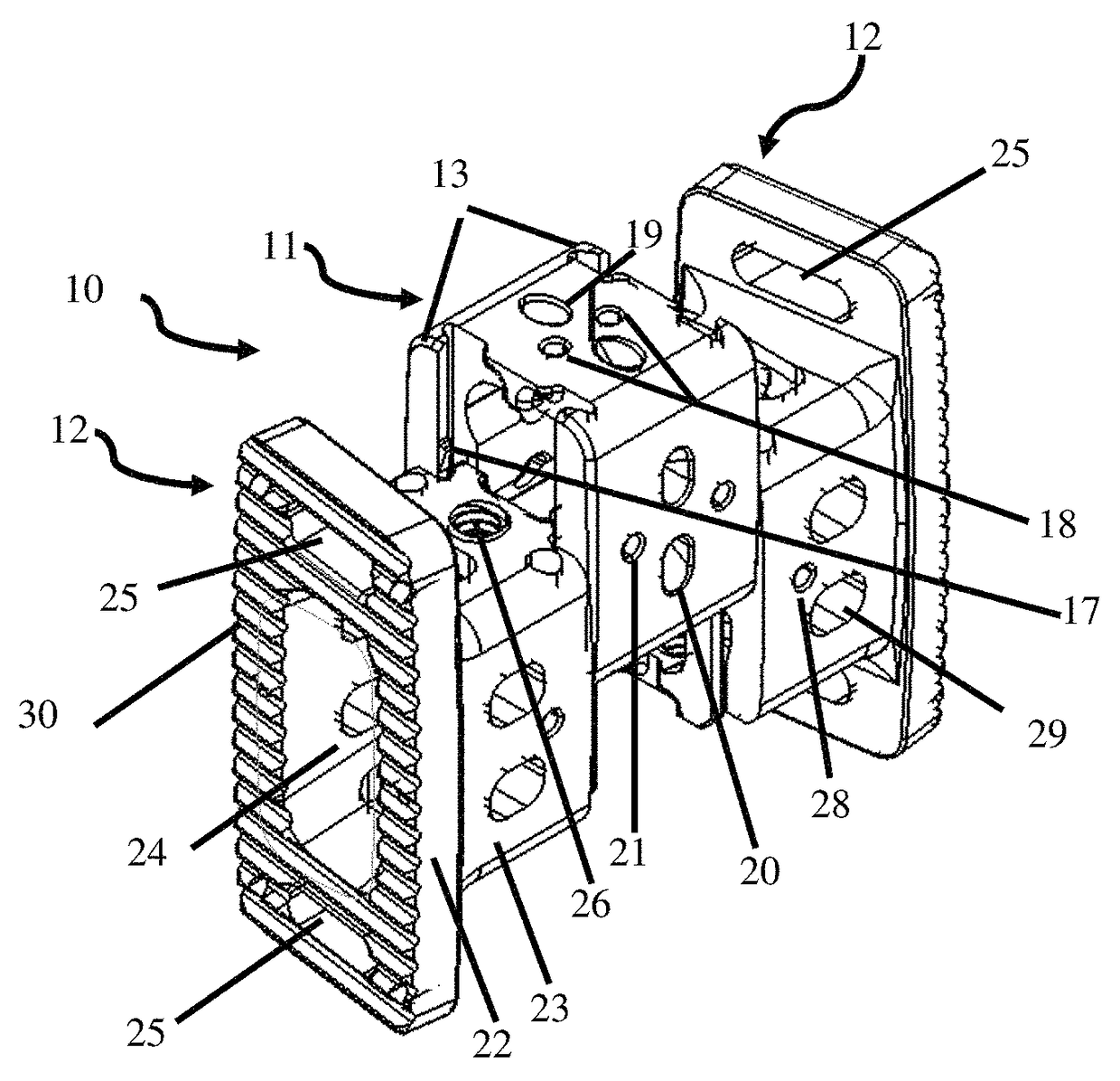
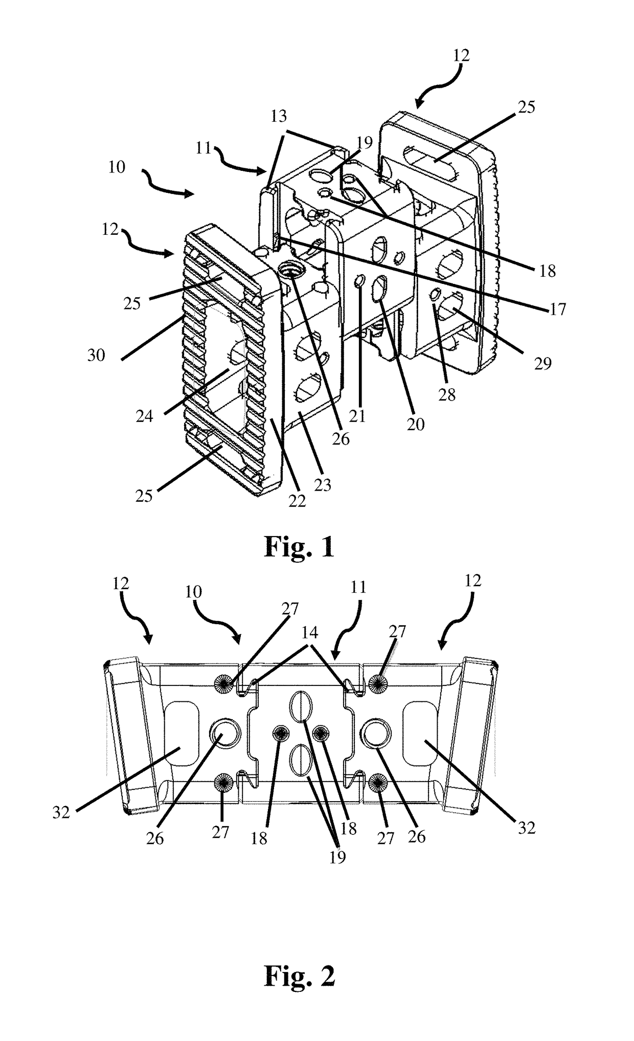
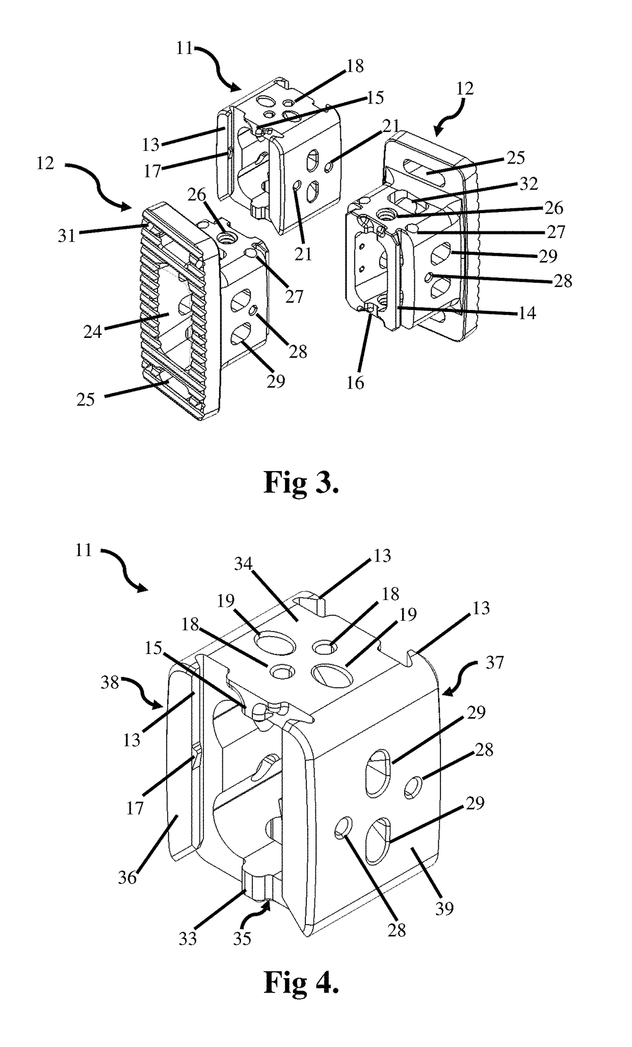
The patent describes a spine replacement system that allows for minimally invasive surgery and faster recovery times for patients. The system includes a lateral inserter assembly, an anterior inserter assembly, and a distractor / sizer assembly. The lateral inserter assembly is made of stainless steel and is used to properly position the endcaps in the body and guide the core between them. The center core of the vertebral body replacement is attached and removed from the tool using a quick-release mechanism. The two endcaps are attached to the lateral inserter assembly using screws and slots. The distractor / sizer assembly is used to open the space between two adjacent vertebrae where the vertebral body replacement will be inserted. The tool is unique because it not only distracts the spinal column, but also measures the desired size of the implant. The measurement can be read from the handles of the tool. The spreader arms of the distractor / sizer have anti-migration elements to hold onto the surface of remaining vertebrae during distraction. The system provides a smaller opening for access to the spine, reduces patient recovery time, and provides many of the benefits of the lateral approach at a lower cost than expandable cages.

Problems solved by technology

Even slight disruptions to either the intervertebral discs or vertebrae can result in serious discomfort due to decompression of nerve fibers either within the spinal cord or extending from the spinal cord.
If a disruption to the spine becomes severe enough, damage to a nerve or part of the spinal cord may occur and can result in partial to total loss of bodily functions (e.g. walking, talking, and breathing).
Trauma to the spine (e.g. car accident, sports injury) can cause fracturing of one or more of the vertebrae.
Both trauma and degeneration may result in severe disruption to the spine.

Method used


Image

  • Vertebral body replacement and insertion methods
  • Vertebral body replacement and insertion methods
  • Vertebral body replacement and insertion methods

Examples


Embodiment Construction

[0055]Illustrative embodiments of the invention are described below. In the interest of clarity, not all features of an actual implementation are described in this specification. It will of course be appreciated that in the development of any such actual embodiment, numerous implementation-specific decisions must be made to achieve the developers' specific goals, such as compliance with system-related and business-related constraints, which will vary from one implementation to another. Moreover, it will be appreciated that such a development effort might be complex and time-consuming, but would nevertheless be a routine undertaking for those of ordinary skill in the art having the benefit of this disclosure. The stackable vertebral body replacement, anterior and lateral inserter assemblies, distractor / sizer and methods for implantation disclosed herein boasts a variety of inventive features and components that warrant patent protection, both individually and in combination.

[0056]FIG...


PUM


Abstract

A vertebral body replacement device, dimensioned for implantation between a first and second vertebral bone is described. The vertebral body replacement device includes a superior endcap, an inferior endcap and a central core between the superior and inferior endcaps. The vertebral body replacement device further includes a fusion aperture extending through the superior and inferior endcaps and central core. The vertebral body replacement device is made of radiolucent material and can be implanted from a lateral or anterior approach to the spine.

Description

CROSS-REFERENCE TO RELATED APPLICATIONS[0001]This application claims the benefit of the filing date of U.S. Provisional Application No. 61 / 454,571, which was filed on Mar. 20, 2011. The contents of U.S. Application No. 61 / 454,571 are incorporated by reference as part of this application.BACKGROUND OF THE INVENTION[0002]I. Field of the Invention[0003]The present invention relates to spinal implants, implant insertion assemblies, and surgical methods for replacing at least a portion of one or more vertebral bodies of the spine.[0004]II. Discussion of the Prior Art[0005]The spine is formed of a column of vertebra that extends between the cranium and pelvis. The three major sections of the spine are known as the cervical, thoracic and lumbar regions. There are 7 cervical vertebrae, 12 thoracic vertebrae, and 5 lumbar vertebrae, with each of the 24 vertebrae being separated from each other by an intervertebral disc. A series of about 9 fused vertebrae extend from the lumbar region of the...

Claims


Application Information

Patent Timeline
Patent Type & Authority Patents(United States)
IPC IPC(8): A61F2/44
CPCA61F2/44A61F2002/443A61B17/025A61F2/4611A61F2/4637A61B2017/0256A61F2002/3008A61F2002/30387A61F2002/30604A61F2002/4627A61F2002/4628A61F2002/4629A61F2002/4658A61B2090/061A61F2002/30593
Inventor SMITH, WILLIAM D.ARNOLD, BENJAMINZATTA, DANIELMALIK, JEREMYALBERT, MORTON B.
Owner NUVASIVE
Learn More