
System and method for prepolarizing magnetic resonance- or relaxation-based measurements

a magnetic resonance or prepolarizing field technology, applied in the field of magnetic resonance imaging (mri), nuclear magnetic resonance spectroscopy, can solve the problems of combining shielding and high prepolarizing fields, affecting measurement accuracy, and affecting measurement accuracy

Active Publication Date: 2017-06-20
AALTO UNIV FOUND
View PDF7 Cites 8 Cited by
  • Summary
  • Abstract
  • Description
  • Claims
  • Application Information

AI Technical Summary

Benefits of technology

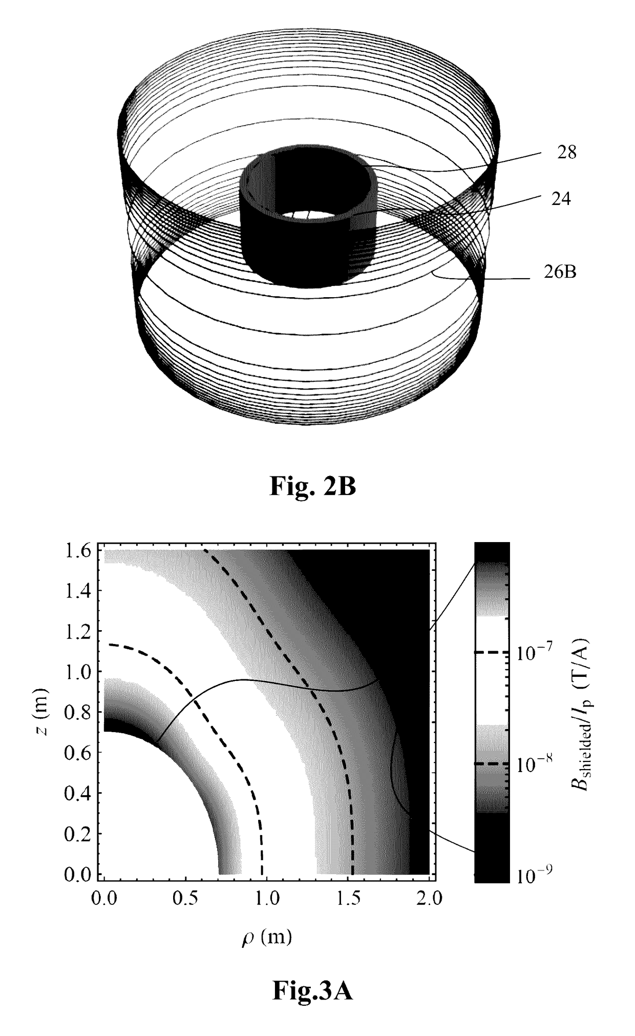
[0025]Alternatively, the shielding coil can be a separate coil, to which current waveforms are actively fed separately to cancel the effects of the polarizing coil in surrounding conducting structures. This approach is called dynamic shielding or dynamic compensation in the following text. In dynamic shielding, the shielding and polarization coils are pulsed in a way that creates a desired polarizing field but harmful transients are made small. Dynamic shielding pulses can be designed for lower power, voltage, or current, or more effective polarization, or other desired properties compared to non-dynamic shielding. Dynamic shielding pulses can also be used to help relax coil design constraints.
[0058]Typically, the apparatus of the present kind is placed in a magnetically shielded room comprising one or more conductive layers intended to prevent external magnetic signals from interfering with the measurement. The shielding coil is optimized to prevent the formation of eddy currents in these conductive layers.

Problems solved by technology

The eddy currents cause magnetic interference in the sample and measurement equipment and may therefore disturb the measurement.
Even if the detectors would not be disturbed, the eddy currents may be detrimental as they may destroy the spin dynamics in the sample to be imaged and set a practical limit for the strength and switch-off time of the prepolarizing field.
In early studies, this has had the effect that the prepolarizing coils have been designed to be small and therefore not suitable for brain research, for example.
However, combining the shielding and high prepolarizing fields is problematic.
If these fields are strong, they will affect the spin dynamics of the sample, reducing image quality, or, in the worst case, making image reconstruction practically impossible.
A large drifting magnetic field may also exceed the dynamic range of the sensors.
In addition, such fields typically contain low-frequency components; thus, they may interfere with MEG recordings, frustrating simultaneous MEG-MRI.
Eddy currents affect the field homogeneity and stability, producing image artifacts.
These methods are not directly applicable to the prepolarizing coil in ULF MRI, prepolarized MRI, ULF NMR, prepolarized NMR, MNI, MRX, or, in particular, ULF MRI combined with MEG.
However, such a design becomes impractical when the sample volume and the strength of the polarizing field increase.
The discussed geometry is, however, not suitable for prepolarized ULF MRI or MRX, for example, in which the prepolarizing coil is typically a solenoid or other coil whose dipole moment is very large.
This approach is, however, quite impractical to implement in practice.
Even more inconvenient, but in theory possible, would be to carry out the polarization and measurement of the sample at different locations.

Method used


Image

  • System and method for prepolarizing magnetic resonance- or relaxation-based measurements
  • System and method for prepolarizing magnetic resonance- or relaxation-based measurements
  • System and method for prepolarizing magnetic resonance- or relaxation-based measurements

Examples


experimental verification

[0123]The invention was tested using a cylindrical polarizing coil with Np=211 turns of 3-mm copper wire in five layers, height hp=0.14 m, and inner and outer radii sin=0.105 m and sout of 0.12 m, respectively. The polarizing coil, with its axis in the vertical direction was located approximately at the center of a double-layer MSR. Both layers had an inner mu-metal shell and an outer aluminum shell. The height, width, and length of the innermost shielding layer were 2.76, 3.11, and 4.11 m, respectively.

[0124]The current in the polarizing coil was switched off rapidly with a dedicated circuit allowing one to reduce the polarizing field nearly linearly to zero in 1 ms. Such a rapid decay induced eddy currents in conductive materials, most notably in the aluminum layers of the magnetically shielded room around the measurement instrument.

[0125]The setup comprised three planar sensor modules, each having two orthogonal SQUID gradiometers, with a baseline of 18 mm and pickup loops compri...


PUM


Abstract

The invention relates to a prepolarizing magnetic resonance- or relaxation-based measurement system, comprising a prepolarizing coil for producing a prepolarizing field at the target zone, means for pulsing the prepolarizing field according to a first pulsing scheme, and means for measuring magnetization of a target placed in the target zone. According to the invention, the system further comprises a shielding coil for producing a shielding field and means for pulsing the shielding field according to a second pulsing scheme, whereby the shielding coil and the second pulsing scheme are arranged to reduce the formation of unwanted transient fields caused by the coupling of the prepolarizing coil to conducting or magnetic structures in the surroundings of the system. The invention also relates to a corresponding method of measurement and a process of designing the pulsing schemes for the system or process. By means of the invention, the formation of unwanted eddy currents, for example, in the surroundings of the measurement system, can be reduced.

Description

FIELD OF THE INVENTION[0001]The invention relates to magnetic resonance imaging (MRI), nuclear magnetic resonance (NMR) spectroscopy and other studies where a sample has to be magnetically polarized. In particular, the invention relates to reducing the unwanted effects of stray magnetic fields in prepolarized MRI with a novel polarisation coil arrangement. The invention is designed, in particular, to be applied in ultra-low-field (main magnetic field B0<10 mT, in particular <1 mT) MRI (ULF MRI). Systems of the present kind comprise the features of the preamble of claim 1.BACKGROUND OF THE INVENTION[0002]Magnetic resonance imaging is capable of producing images of inner structure of matter. MRI is frequently used in hospitals and other medical or research facilities for diagnosing diseases and for research purposes. Remarkable exemplary areas of use are cancer diagnosis and brain research. ULF MRI has recently shown potential in these areas due to its excellent contrast between...

Claims


Application Information

Patent Timeline
Patent Type & Authority Patents(United States)
IPC IPC(8): G01R33/58G01R33/44G01R33/421G01R33/42
CPCG01R33/583G01R33/42G01R33/421G01R33/445
Inventor NIEMINEN, JAAKKOZEVENHOVEN, CORNELISVESANEN, PANUILMONIEMI, RISTO
Owner AALTO UNIV FOUND
Learn More