Telecommunication antenna reflector for high-frequency applications in a geostationary space environment

a technology of geostationary space and telecommunication antenna, which is applied in the field of telecommunication satellites, can solve the problems of not being able to oversize the reflector to improve the gain, the assembly of this type of structure, and the size and mass of the space to be sent into space, so as to facilitate the assembly of the angular sector, reduce the number of labor hours, and reduce the effect of thermoplastic deformation

Active Publication Date: 2017-06-06
THALES SA
View PDF8 Cites 0 Cited by
  • Summary
  • Abstract
  • Description
  • Claims
  • Application Information

AI Technical Summary

Benefits of technology

[0032]The use of a single fibre composite material guarantees low thermoplastic deformation.
[0033]The rim formed at the periphery of the active surface acts as a stiffening ring directly incorporated into the reflector, thereby avoiding the drawbacks encountered in so-called “monolithic technology with peripheral stiffener” that are related to the production of moulds and to the cold-adhesive bonding of the ring onto the active surface. In fact, the reflector thus produced makes it possible to limit the number of labour hours necessary.
[0034]Advantageously the reflector comprises at least one layer possessing a central part centered on the center, which facilitates the assembly of the angular sectors and prevents the angular sectors from overlapping at the center of the reflector.

Problems solved by technology

For satellites, the gains required are smaller (of the order of 40 to 50 dB), but the main limiting factors are the size and mass to be sent into space.
In fact it is not possible to oversize the reflectors to improve the gain.
This design is especially competitive for reflectors with a diameter between 1 and 2 m. The assembly of this type of structure is, however, too complex and therefore too expensive for reflectors of small diameter.
This technology also requires the use of a large quantity of adhesive, which is not compatible with applications at high temperatures.
Moreover, a reflector of a diameter of 500 mm manufactured using the so-called “thick shell” technology weighs 550 g. This technology does not make it possible to attain the weight targets set for applications in a space environment.
On the other hand, this technology performs poorly where weight targets are concerned.
The complexity of assembly of the reinforcement grid means that this technology does not perform well from an economic point of view for reflectors of small diameter, in the same way as the so-called “thick shell” technology.
This solution brings an improvement in terms of the weight of the reflector, though the process of assembly and manufacture is not optimized.
Moreover, the cold-adhesive bonding of the peripheral stiffening ring onto the active face of the reflector limits the range of use temperatures.

Method used


Image

  • Telecommunication antenna reflector for high-frequency applications in a geostationary space environment
  • Telecommunication antenna reflector for high-frequency applications in a geostationary space environment
  • Telecommunication antenna reflector for high-frequency applications in a geostationary space environment

Examples


Embodiment Construction

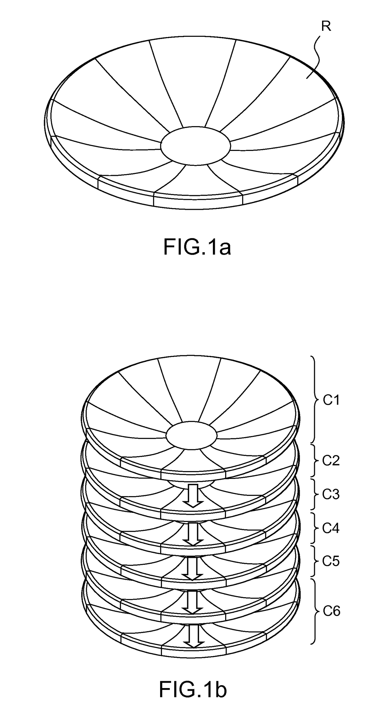
[0054]FIG. 1a illustrates a reflector R, comprising a fibrous material M of paraboloidal shape comprising a rim, the diameter of the reflector R being between 250 and 700 mm, and preferably 500 mm. Alternatively, the reflector can be of ellipsoidal shape.

[0055]The concave surface of the layer constitutes the reflective surface of the reflector R and is oriented towards the terrestrial globe. The rim acts as a stiffening ring enabling the structure to be stiffened and resonant frequencies of 60 Hz to be attained at a temperature of 20° C.

[0056]FIG. 1b highlights the component elements of the reflector R. The reflector R comprises a stack of at least one layer Cn. Advantageously, the stack comprises between 2 and 10 layers, the number of layers Cn depending on the type of material used. The required mechanical performance levels can be obtained by considering a superposition of six layers C1-C6.

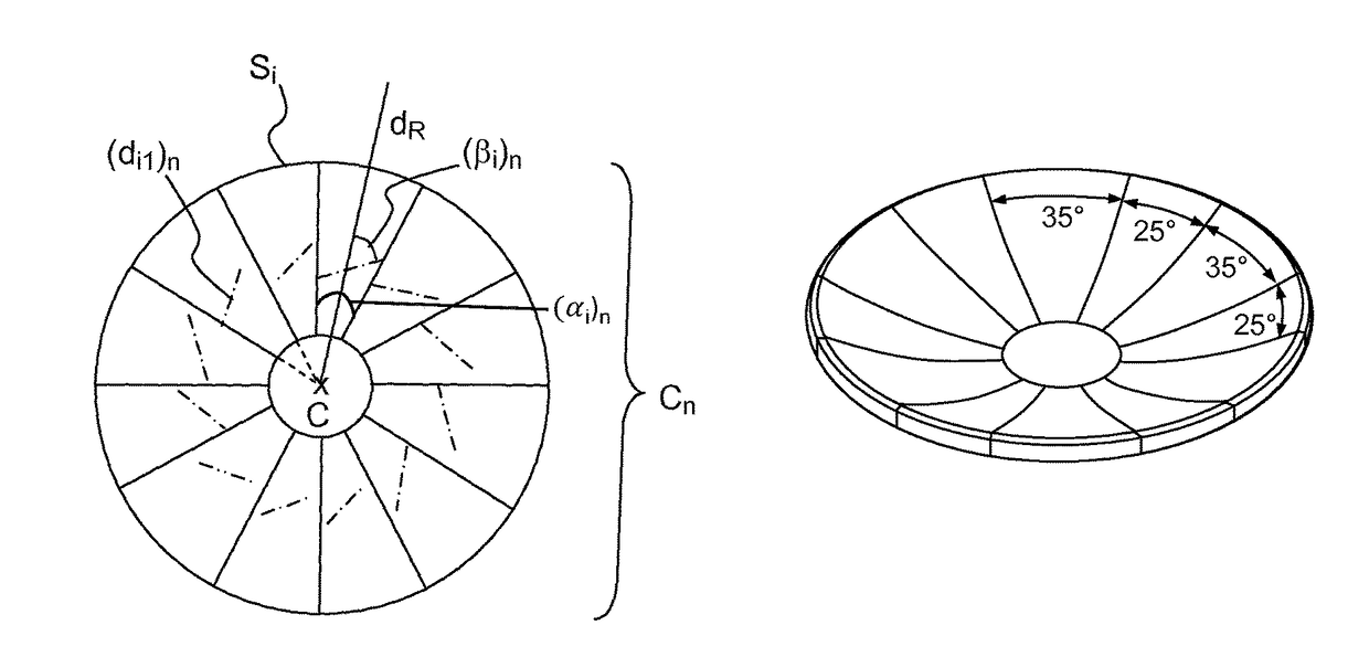
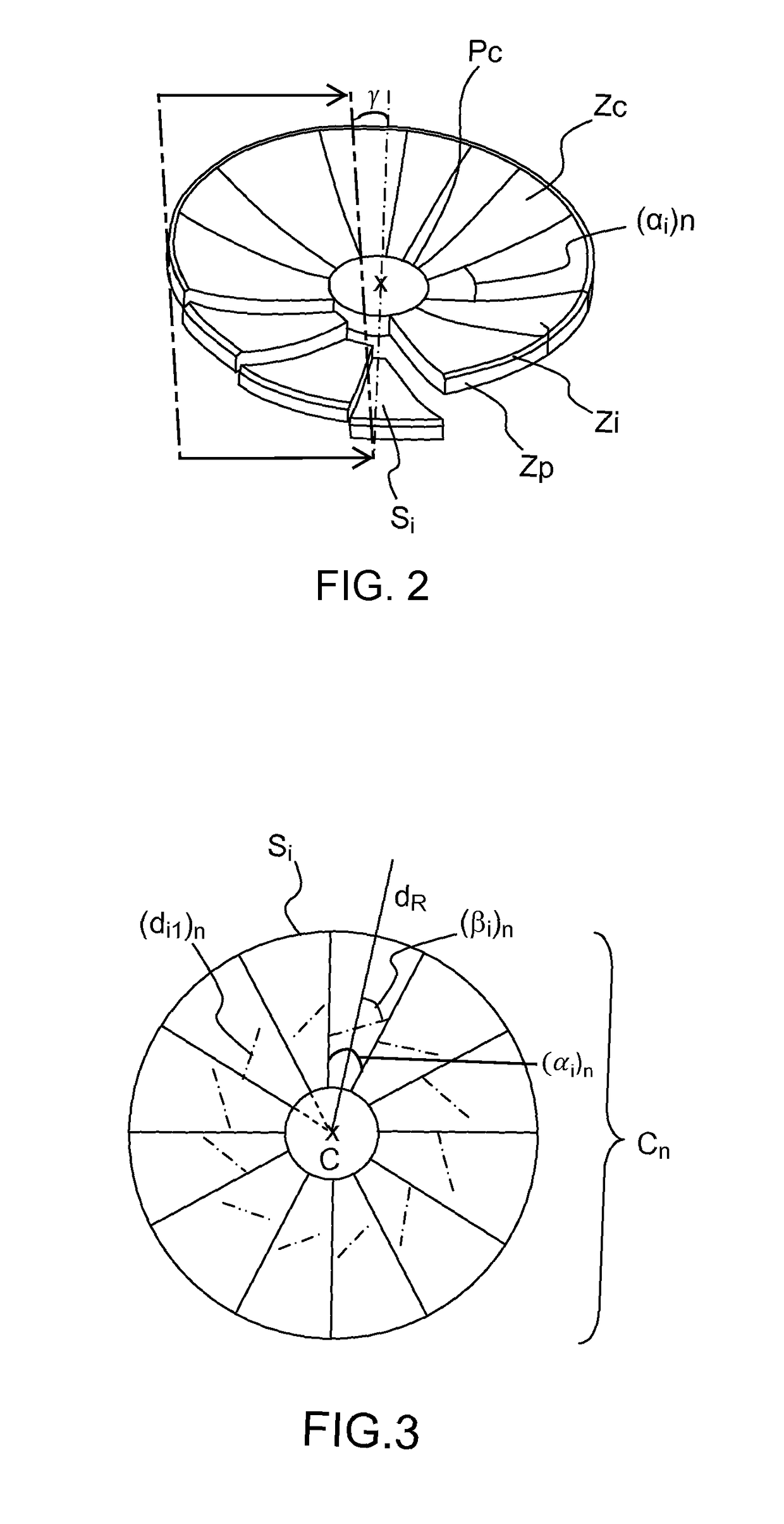
[0057]FIG. 2 illustrates the different component parts of a layer Cn.

[0058]A layer Cn compr...


PUM


Abstract

An antenna reflector compatible with applications at high frequencies between 12 and 75 GHz and suitable for a paraboloidal or ellipsoidal geostationary space environment comprising a reflective face to focus electromagnetic radiation, comprises a superposition of at least one layer comprising a fiber composite material, the at least one layer of fiber composite material comprising angular sectors arranged around a center, each defined by a first central angle and oriented in a radial direction the median of the central angle, each of the angular sectors comprising the fiber composite material comprising first and second fibers oriented different first and second respective directions, the first direction forming a second angle with the radial direction of the angular sector. The angular sectors comprise three concentric areas: a central area, a peripheral area and an intermediate area situated between the central area and the peripheral area, the intermediate area forming a rim.

Description

CROSS-REFERENCE TO RELATED APPLICATION[0001]This application claims priority to foreign French patent application No. FR 1201995, filed on Jul. 13, 2012, the disclosure of which is incorporated by reference in its entirety.FIELD OF THE INVENTION[0002]The invention lies in the field of telecommunication satellites comprising passive antennas equipped with reflectors. The invention is particularly intended for applications in very high frequency bands of Ka and Q / V type but also meets the lesser technical requirements of the Ku frequency band.BACKGROUND[0003]The frequency band denoted Ku corresponds to frequencies between 12 and 18 GHz, or wavelengths between 2.5 and 1.6 cm. The frequency band denoted Ka corresponds to frequencies between 26.5 and 40 GHz or wavelengths between 11.3 and 7.5 mm.[0004]The frequency band denoted Q / V corresponds to frequencies between 33 and 75 GHz or wavelengths between 9.1 and 3.3 mm.[0005]There are a large number of applications involving reflector ante...

Claims


Application Information

Patent Timeline
Patent Type & Authority Patents(United States)
IPC IPC(8): H01Q15/14H01Q1/28H01Q15/16
CPCH01Q15/14H01Q1/288H01Q15/141H01Q15/168H01Q15/165
Inventor LEBRUN, FLORENTMARTINEAU, PATRICK
Owner THALES SA
Why Eureka
Try Eureka