
Image forming apparatus

a technology of image forming and forming drums, which is applied in the direction of electrographic process apparatus, corona discharge, instruments, etc., can solve the problems of image deterioration called image memory, the difficulty of color printing mode uniform charging of the surface of the photosensitive drum for y, m and c colors, and the damage of the photosensitive drum. , to achieve the effect of reducing the influence of a life of the photosensitive drum and/or image deterioration

Active Publication Date: 2017-06-06
KONICA MINOLTA INC
View PDF15 Cites 0 Cited by
  • Summary
  • Abstract
  • Description
  • Claims
  • Application Information

AI Technical Summary

Benefits of technology

[0012]For solving the aforementioned problems, an object of the present invention is to provide an image forming apparatus capable of reducing influence on a life of a photosensitive drum and / or image deterioration.

Problems solved by technology

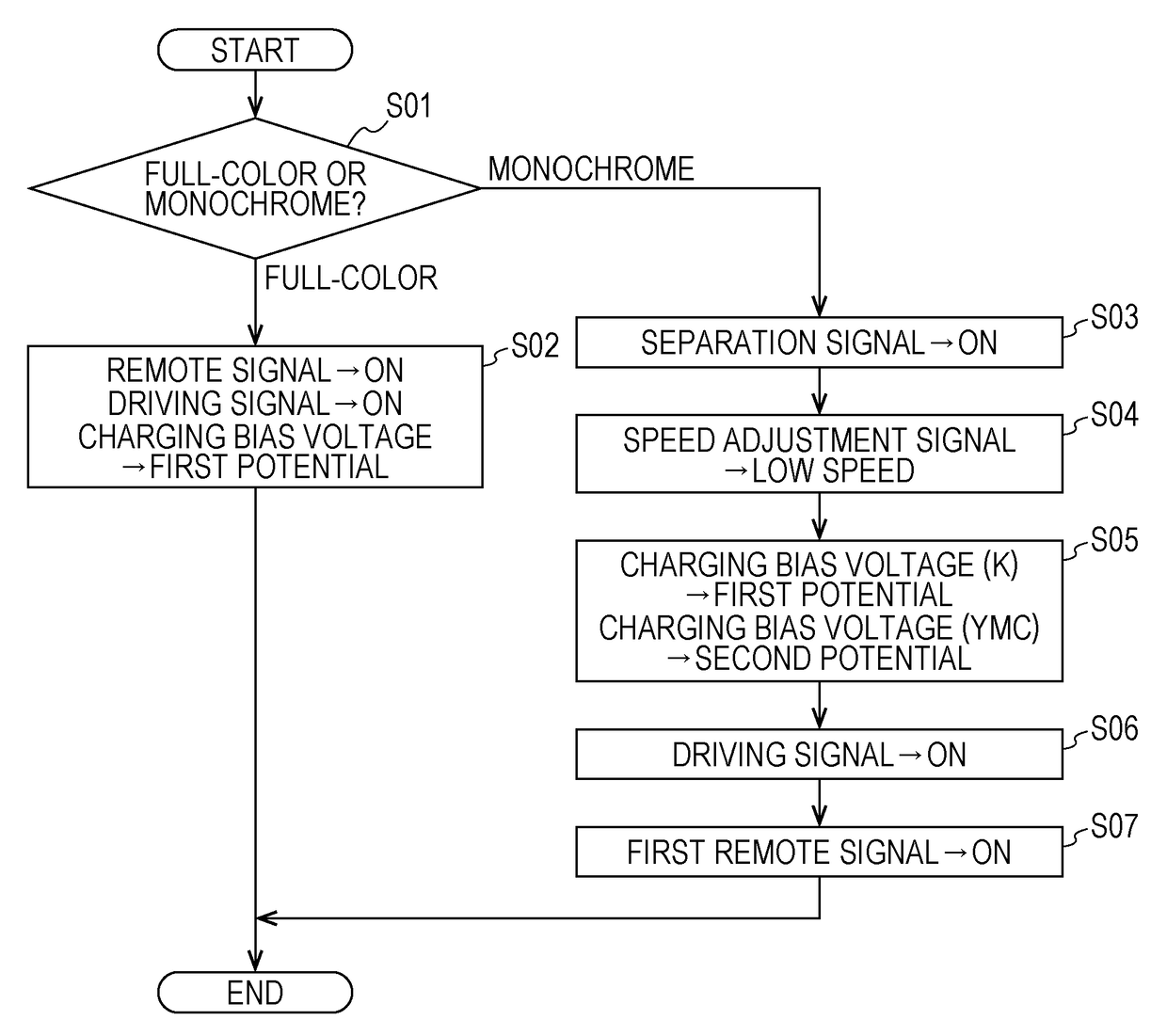
According to this conventional image forming apparatus, however, electric damage (more specifically, film reduction) may be given to the photosensitive drums for Y, M, and C colors particularly at positions facing the developing rollers for Y, M, and C colors when the developing bias voltage is constantly supplied to the developing rollers for Y, M, and C colors from the high-voltage power supply circuit in a rotation stop state of the photosensitive drums for Y, M, and C colors in a monochrome printing mode.
When the charging bias voltage and the primary transfer bias voltage are constantly supplied to the charging units and the primary transfer rollers for Y, M, and C colors in the monochrome printing mode in this structure, uniform charging for the surfaces of the photosensitive drums for Y, M, and C colors becomes difficult in the subsequent color printing mode.
In this case, image deterioration called an image memory may be caused.

Method used


Image

  • Image forming apparatus
  • Image forming apparatus
  • Image forming apparatus

Examples


first embodiment

Section 3: High-Voltage Power Supply Circuit and Control Circuit in First Embodiment

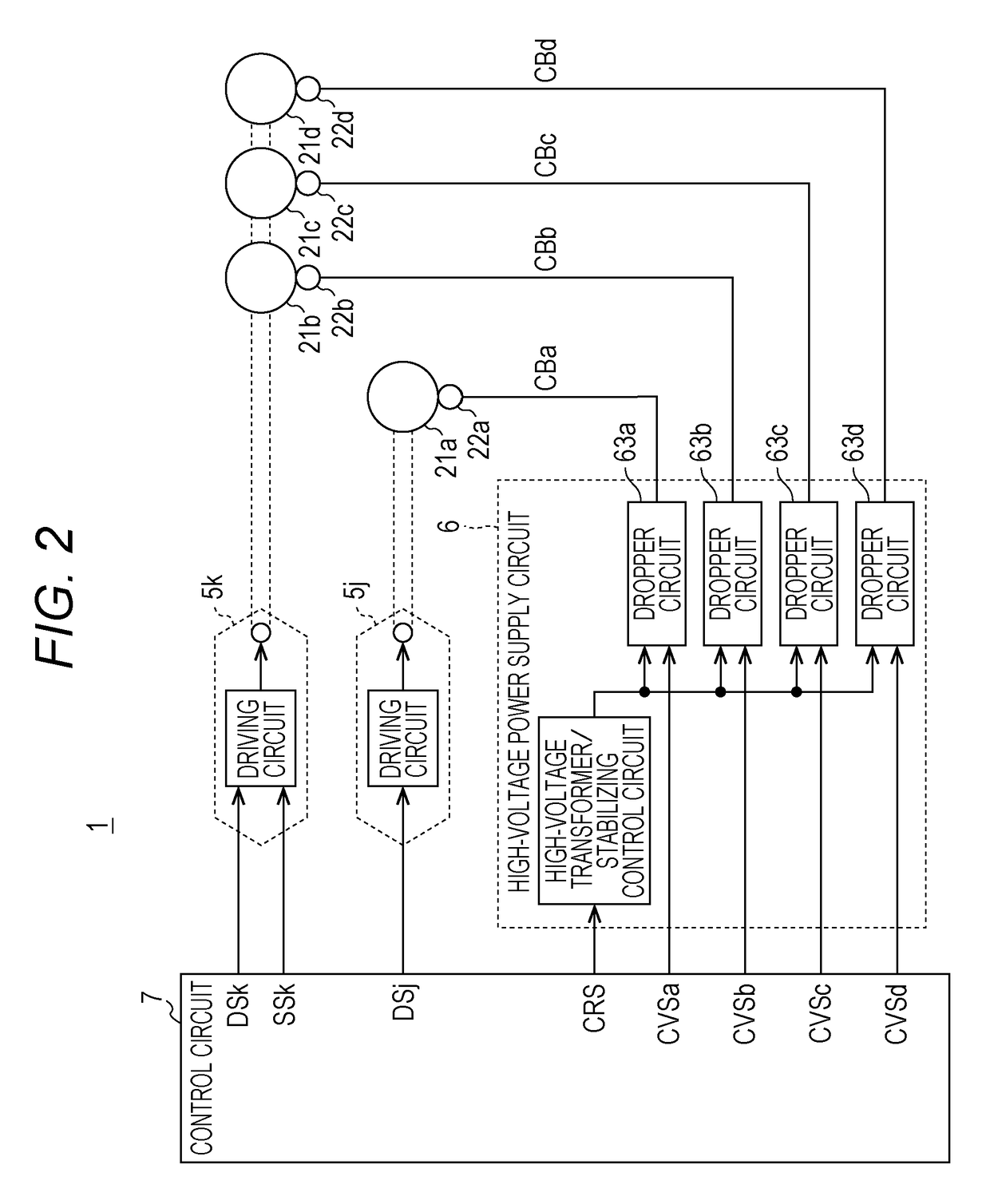
[0053]According to the first embodiment, the image forming apparatus 1 includes a high-voltage power supply circuit 6 and the control circuit 7 as illustrated in FIG. 2. The high-voltage power supply circuit 6 includes a single first high-voltage transformer 61, a first stabilizing control circuit 62, and first dropper circuits 63a through 63d as illustrated in FIG. 3.

[0054]The high-voltage transformer 61 is a common transformer used by the charging units 22a through 22d corresponding to the processing components of the same type. The high-voltage transformer 61 generates a predetermined high voltage based on a voltage applied to the primary side (such as constant voltage of +24V), and outputs the generated high voltage to the secondary side under the control of the stabilizing control circuit 62. The voltage output from the high-voltage transformer 61 is rectified by a diode, smoothed by a capacitor...

second embodiment

Section 6: High-Voltage Power Supply Circuit and Control Circuit in Second Embodiment

[0076]The image forming apparatus 1 according to a second embodiment is different from the image forming apparatus 1 in the first embodiment in that the high-voltage power supply circuit 6 further includes a configuration associated with the developing units 24a through 24d as illustrated in FIG. 6. Other configurations are similar to the corresponding configurations in the first embodiment. Configurations in FIG. 6 similar to the corresponding configurations illustrated in FIG. 2 have been given similar reference numbers, and the same explanation is not repeated herein.

[0077]As illustrated in FIG. 7, the high-voltage power supply circuit 6 includes a second high-voltage transformer 61A, a second stabilizing control circuit 62A, and a second dropper circuit 63A, in addition to the configuration illustrated in FIG. 3.

[0078]The high-voltage transformer 61A is a common transformer used by the developin...

third embodiment

Section 9: High-Voltage Power Supply Circuit and Control Circuit in Third Embodiment

[0086]As illustrated in FIG. 10, the image forming apparatus 1 according to a third embodiment is different from the image forming apparatus 1 in the first embodiment in that the high-voltage power supply circuit 6 includes a configuration associated with the primary transfer rollers 25a through 25d instead of the configuration associated with the charging units 22a through 22d. Other configurations are similar to the corresponding configurations in the first embodiment. Configurations in FIG. 10 similar to the corresponding configurations illustrated in FIG. 2 have been given similar reference numbers, and the same explanation is not repeated herein.

[0087]As illustrated in FIG. 11, the high-voltage power supply circuit 6 includes a single third high-voltage transformer 61B, a third stabilizing control circuit 62B, and third dropper circuits 63Ba through 63Bd.

[0088]The high-voltage transformer 61B is...


PUM


Abstract

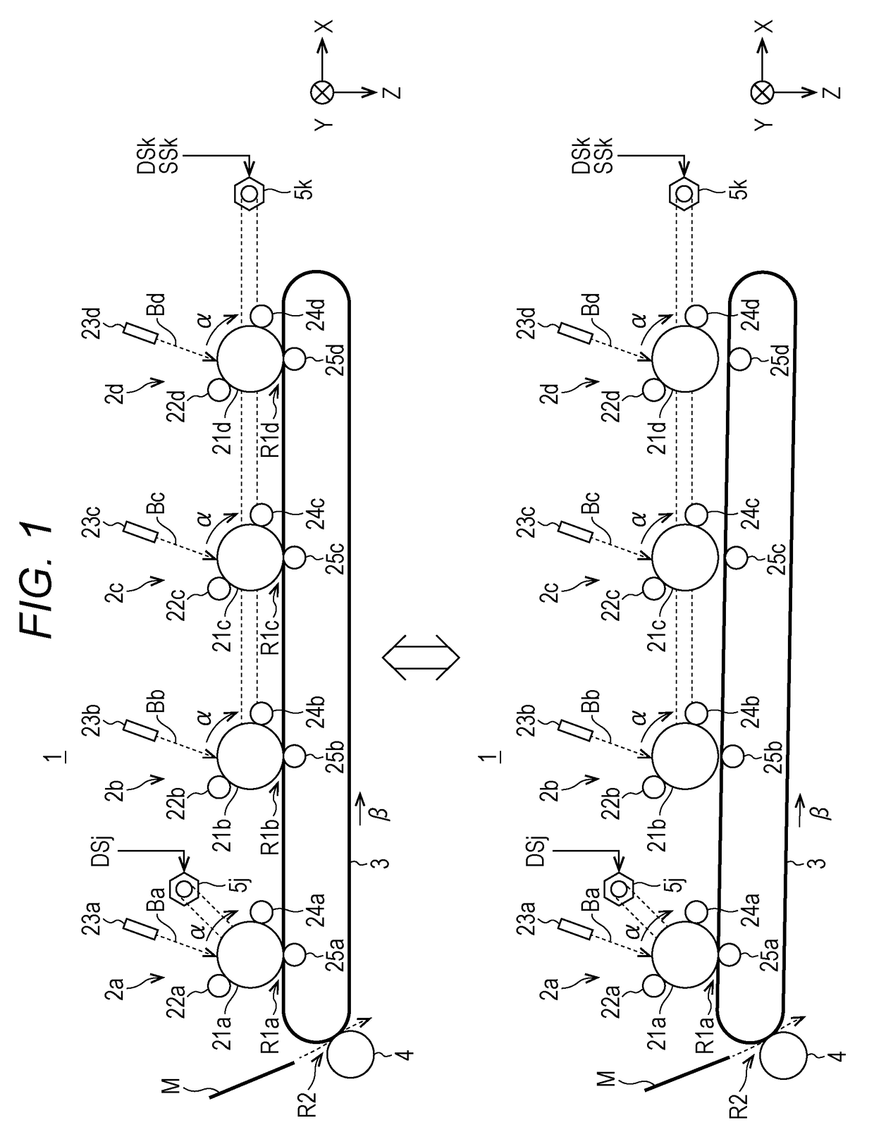
An image forming apparatus includes: a plurality of image forming units forming an image in the corresponding color by electrophotographic system; a high-voltage power supply circuit capable of generating a bias voltage; and a control unit that controls a first printing mode and a second printing mode, wherein in the second printing mode, the control unit performs such control that the photosensitive bodies provided on the image forming units not used in the second printing mode continuously rotate at a speed lower than a speed in the first printing mode, and / or such control that a bias voltage whose absolute value is less than an absolute value of a bias voltage in the first printing mode is supplied from the high-voltage power supply circuit to the processing components of the same type provided on the image forming units not used in the second printing mode.

Description

[0001]The entire disclosure of Japanese Patent Application No. 2014-234919 filed on Nov. 19, 2014 including description, claims, drawings, and abstract are incorporated herein by reference in its entirety.BACKGROUND OF THE INVENTION[0002]Field of the Invention[0003]The present invention relates to an image forming unit which includes a high-voltage power supply circuit capable of generating a bias voltage based on a voltage output from a common transformer used by a plurality of image forming units, and applying the generated bias voltage to the same type of processing components provided on the image forming units.[0004]Description of the Related Art[0005]There is known an image forming apparatus which adopts a tandem system for realizing full-color printing, for example. This type of image forming apparatus includes an image forming unit for each color of Y (yellow), M (magenta), C (cyan), and K (black). These image forming units are linearly arranged. In these units, the image fo...

Claims


Application Information

Patent Timeline
Patent Type & Authority Patents(United States)
IPC IPC(8): G03G15/00G03G15/02G03G15/01
CPCG03G15/0266G03G15/0136G03G15/80G03G15/0178G03G21/14G03G21/1661
Inventor SHIMAZOE, MAKOTOHAYASHI, AKIHIROYOSHIKAWA, HIROYUKIHIGASHI, TOSHIKAZU
Owner KONICA MINOLTA INC
Learn More