
Image forming apparatus capable of reducing recovery printing time

a technology of recovery printing and forming apparatus, which is applied in the direction of electrographic process apparatus, instruments, optics, etc., can solve the problems of affecting the quality of image bearing parts, the delay in the completion of printing, and the delay in the scheduled meeting of print output, so as to reduce the recovery printing time and reduce the abrasion and deterioration of image bearing parts. , the effect of reducing the time of recovery printing

Inactive Publication Date: 2015-04-28
CANON KK
View PDF10 Cites 1 Cited by
  • Summary
  • Abstract
  • Description
  • Claims
  • Application Information

AI Technical Summary

Benefits of technology

The present invention is an image forming apparatus that can reduce recovery printing time while also reducing abrasion and deterioration of the image bearing members. This means that the apparatus can properly achieve these goals and maintain optimal performance.

Problems solved by technology

However, the above-mentioned printing method causes the photosensitive members for color toner to rotate in the state brought into contact with the intermediate transfer belt even in monochrome image formation, which is not preferable in terms of unnecessarily accelerated abrasion and deterioration of the photosensitive members for color toner.
That is, in both of the cases, the same time period is required for the total mode switching time period, and hence the time lost by job interruption e.g. due to a jam is directly added to the total printing time.
However, according to the method of determining the image formation mode disclosed in Japanese Patent No. 3848177, if a job is interrupted, a time period required to clear a jam is added to the total printing time period, and hence completion of printing is largely delayed from the finish time estimated by the user.
As a result, the print output may be late for the scheduled meeting.
This brings about a problem that it is impossible to properly reduce the recovery printing time depending on the situation, and it is impossible to recover the time lost by job interruption.

Method used


Image

  • Image forming apparatus capable of reducing recovery printing time
  • Image forming apparatus capable of reducing recovery printing time
  • Image forming apparatus capable of reducing recovery printing time

Examples


first embodiment

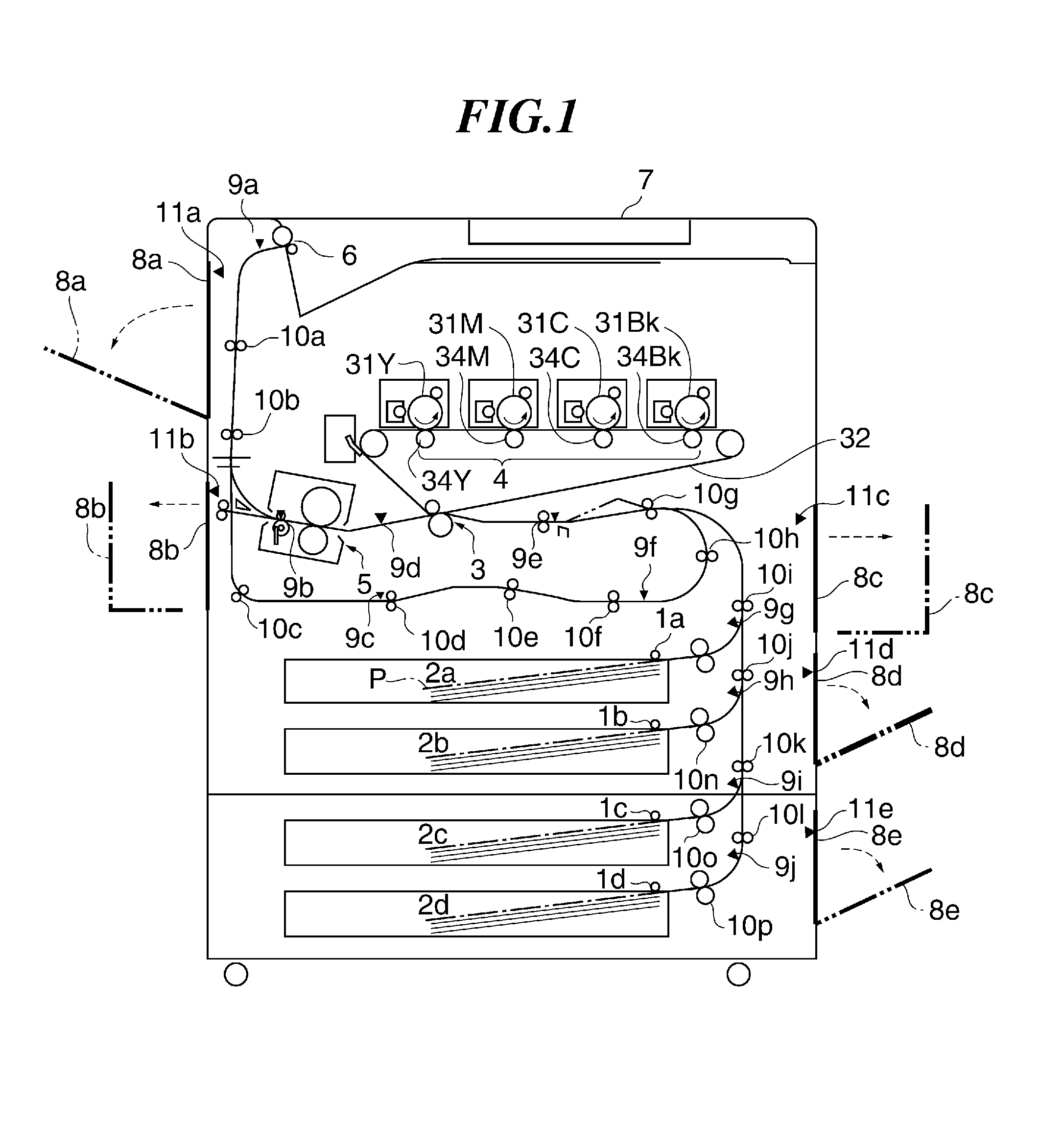
[0046]FIG. 1 is a cross-sectional view of an image forming apparatus according to the present invention.

[0047]The image forming apparatus shown in FIG. 1 is a color image forming apparatus that forms an image of a plurality of colors using an electrophotographic process. First, a description will be given of an outline of the arrangement and operations of the present image forming apparatus.

[0048]Recording sheets P are fed from sheet feeders 2a to 2d by pickup rollers 1a to 1d, respectively. In an image forming section 4, toner images formed on photosensitive members 31 as image baring members are primarily transferred onto an intermediate transfer belt 32 which is a belt member, in a superimposed manner to form a toner image thereon, and the toner image on the intermediate transfer belt 32 is secondarily transferred onto a recording sheet P by a transfer section 3. Then, the toner image transferred onto the recording sheet P is heated and fixed by a fixing section 5, and then the r...


PUM


Abstract

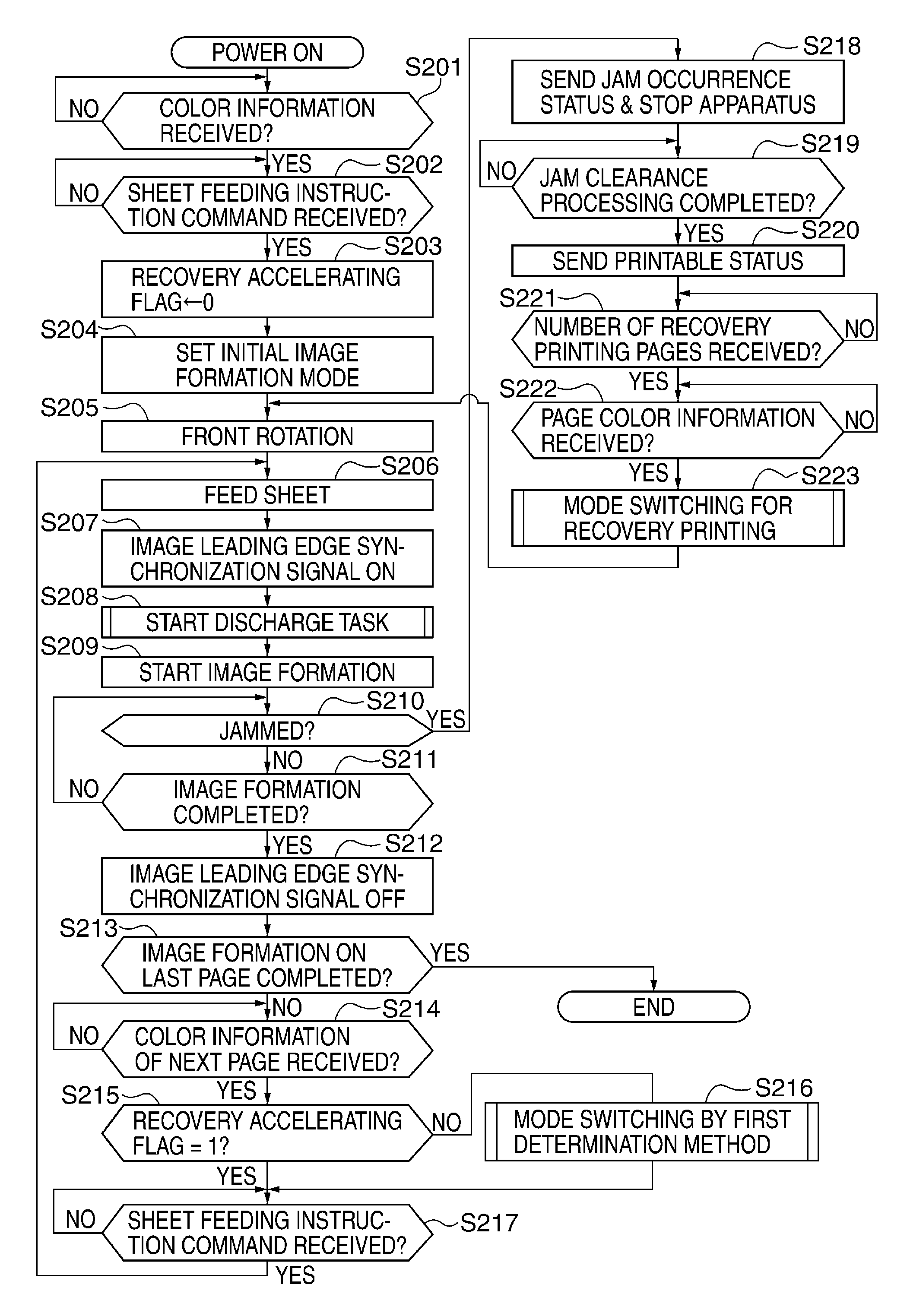
An image forming apparatus capable of properly reducing recovery printing time, while reducing abrasion and deterioration of image bearing members. As an image formation mode determining method, a first method is selected before a print job is interrupted e.g. a jam, whereas for recovery printing, one of the first method and a second method is selected. In the first method, if an image to be formed is a color image, an image formation mode is set to an all-contact mode having an intermediate transfer belt brought into contact with all of photosensitive members, and if the image is a monochrome image, the mode is set to a partial-contact mode having the belt brought into contact only with a photosensitive member for black toner. In the second method, the mode is set to the all-contact mode for all pages on which image formation is to be performed.

Description

BACKGROUND OF THE INVENTION[0001]1. Field of the Invention[0002]The present invention relates to an image forming apparatus that performs image formation in a plurality of colors, and is capable of reducing recovery printing time.[0003]2. Description of the Related Art[0004]Conventionally, as a color image forming apparatus using an electrophotographic process, there has been known one using a method of primarily transferring a toner image formed on a photosensitive member onto an intermediate transfer belt and thereafter secondarily transferring the toner image on the intermediate transfer belt onto a recording sheet.[0005]For example, in a tandem-type color image forming apparatus, four photosensitive members for yellow toner, magenta toner, cyan toner, and black toner are arranged along a direction of rotating the intermediate transfer belt. Each of the photosensitive members and the intermediate transfer belt are rotated while being in contact with each other, whereby toner imag...

Claims


Application Information

Patent Timeline
Patent Type & Authority Patents(United States)
IPC IPC(8): G03G15/00G03G15/01
CPCG03G15/5012G03G15/0136
Inventor YAKO, YASUHIRO
Owner CANON KK
Learn More