Liquid ejecting apparatus and liquid ejecting method

Active Publication Date: 2009-10-08
SEIKO EPSON CORP
View PDF0 Cites 14 Cited by
  • Summary
  • Abstract
  • Description
  • Claims
  • Application Information

AI Technical Summary

Benefits of technology

[0007]An advantage of some aspects of the invention is to shorten image forming process time while suppressing deterioration in image quality in an image forming process using POL control.
[0010]In accordance with the liquid ejecting apparatus of Application Example 1, the overlap control is canceled when a nozzle forming at least one of the lower end portion of the first dot formation area and the upper end portion of the second dot formation area is positioned at a boundary portion between the blank area and an image forming area having the dots formed thereon. Accordingly, since the first dot formation area and the second dot formation area are not overlapped with each other, the number of overlapped scannings can be reduced, and the image forming process time can be shortened. Since a dot formation area is formed during a single scanning by the image forming section when the overlap control is canceled, dots are not intermittently formed and successively formed on the lower end portion and the upper end portion of the dot formation area. As a result, it is possible to suppress deterioration in image quality of an image formed on a recording medium in the case of canceling the overlap control.
[0011]In the liquid ejecting apparatus of Application Example 1, it is preferable that the image forming section transport the recording medium in the sub-scanning direction, in accordance with a width of the blank area in the sub-scanning direction, after forming the first dot formation area, when the blank area exists. In accordance with the liquid ejecting apparatus of Application Example 1, the recording medium is transported in accordance with a width of the blank area, and thus the number of scannings corresponding to the width of the transported blank area can be reduced. As a result, time necessary to perform scannings of the printing head can be shortened, and thus it is possible to shorten printing time.
[0012]In the liquid ejecting apparatus of Application Example 1, it is preferable that the overlap control section perform the overlap control by forming the dots on the lower end portion of the first dot formation area during the first main scanning on the basis of a first arrangement pattern, which is a pattern for arranging the dots, representing intermittent dot arrangement in a region corresponding to the lower end portion of the first dot formation area, and by forming the dots on the upper end portion of the second dot formation area during the second main scanning on the basis of a second arrangement pattern, which is a pattern for arranging the dots, representing intermittent dot arrangement reverse to the intermittent dot arrangement represented by the first arrangement pattern. In accordance with the liquid ejecting apparatus of Application Example 1, dots are intermittently formed on the basis of the arrangement pattern defining intermittent dot arrangement. As a result, the liquid ejecting apparatus of Application Example 1 is capable of forming dots intermittently on the lower end portion of the first dot formation area and the upper end portion of the second dot formation area so as to supplement each other, with a simple configuration.
[0013]In the liquid ejecting apparatus of Application Example 1, it is preferable that the cancellation section perform intermittent dot formation in the overlap control by forming dots on the basis of a third arrangement pattern representing successive dot arrangement in a region corresponding to at least one end portion, which is positioned on the boundary portion between the blank area and the image forming area, of the lower end portion of the first dot formation area and the upper end portion of the second dot formation so as to successively form the dots on the at least one end portion. In accordance with the liquid ejecting apparatus of Application Example 1, dots are successively formed on the end portions of the dot formation area positioned on the boundary portion between the blank area and the image forming area, on the basis of the third arrangement pattern different from the dot arrangement pattern used for the overlap control. As a result, the liquid ejecting apparatus of Application Example 1 is capable of easily canceling the intermittent dot formation at the time of the overlap control while suppressing deterioration in image quality of the image formed on the recording medium by separately using the arrangement patterns.
[0014]In the liquid ejecting apparatus of Application Example 1, it is preferable that the cancellation section cancel intermittent dot formation in the overlap control by forming dots without use of the first arrangement pattern when the lower end portion of the first dot formation area is positioned on the boundary portion between the blank area and the image forming area and by forming dots without use of the second arrangement pattern when the upper end portion of the second dot formation area is positioned on the boundary portion between the blank area and the image forming area. In accordance with the liquid ejecting apparatus of Application Example 1, the intermittent dot formation at the time of the overlap control is canceled by forming the dot formation area which does not use the dot arrangement pattern. As a result, it is possible to reduce process load of the liquid ejecting apparatus since the nozzle control based on the arrangement pattern is not required in the case of canceling the overlap control.

Problems solved by technology

However, in the band printing method, sometimes stripes appear at the boundaries between the bands.
The stripes cause deterioration in image quality of the image formed on the recording medium.
However, there is a problem in that image quality of a printed image is deteriorated when the blank skip process is applied during a printing process in which the POL control is being performed.

Method used


Image

  • Liquid ejecting apparatus and liquid ejecting method
  • Liquid ejecting apparatus and liquid ejecting method
  • Liquid ejecting apparatus and liquid ejecting method

Examples


first example

A. First Example

A1. Configuration of Printing System

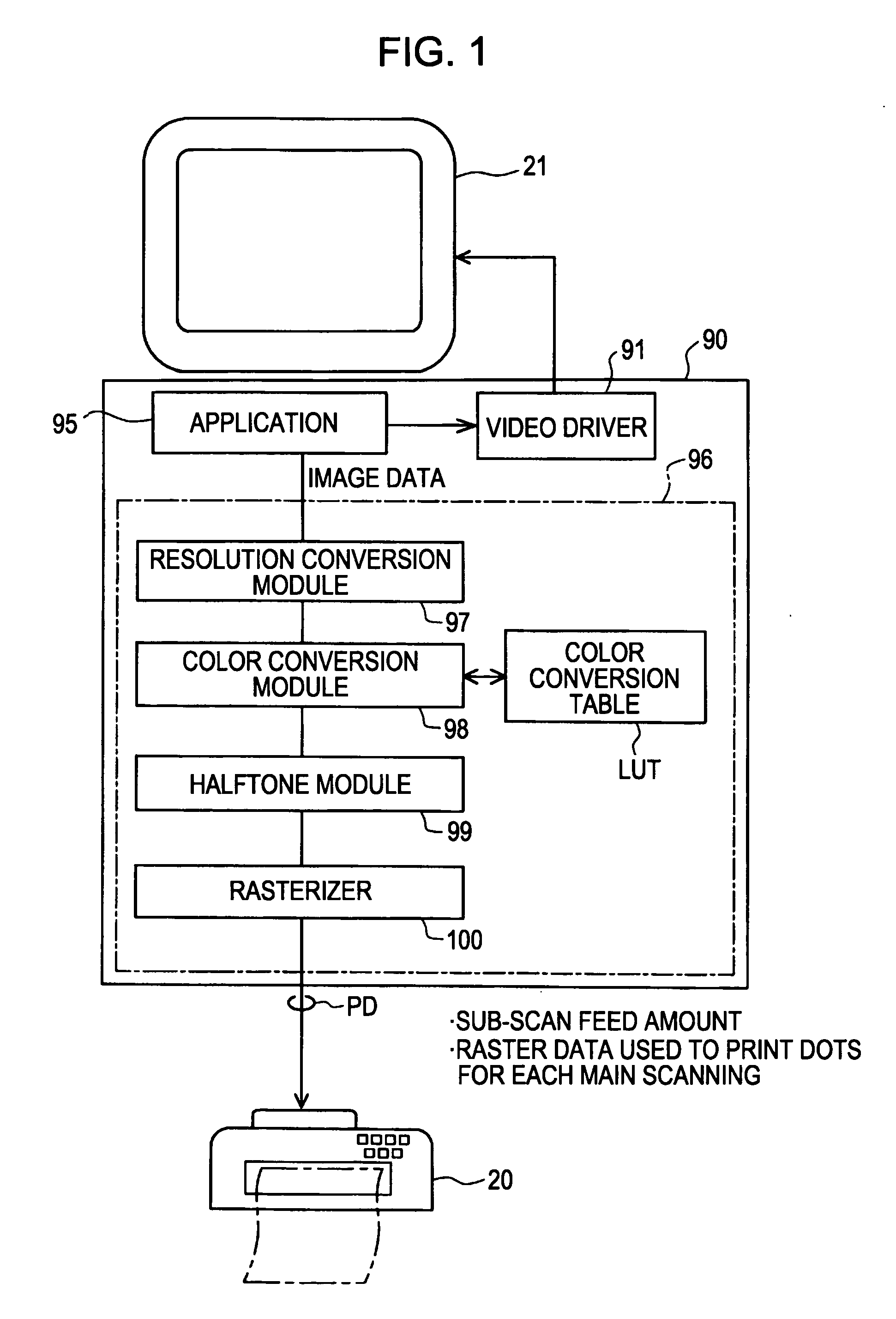
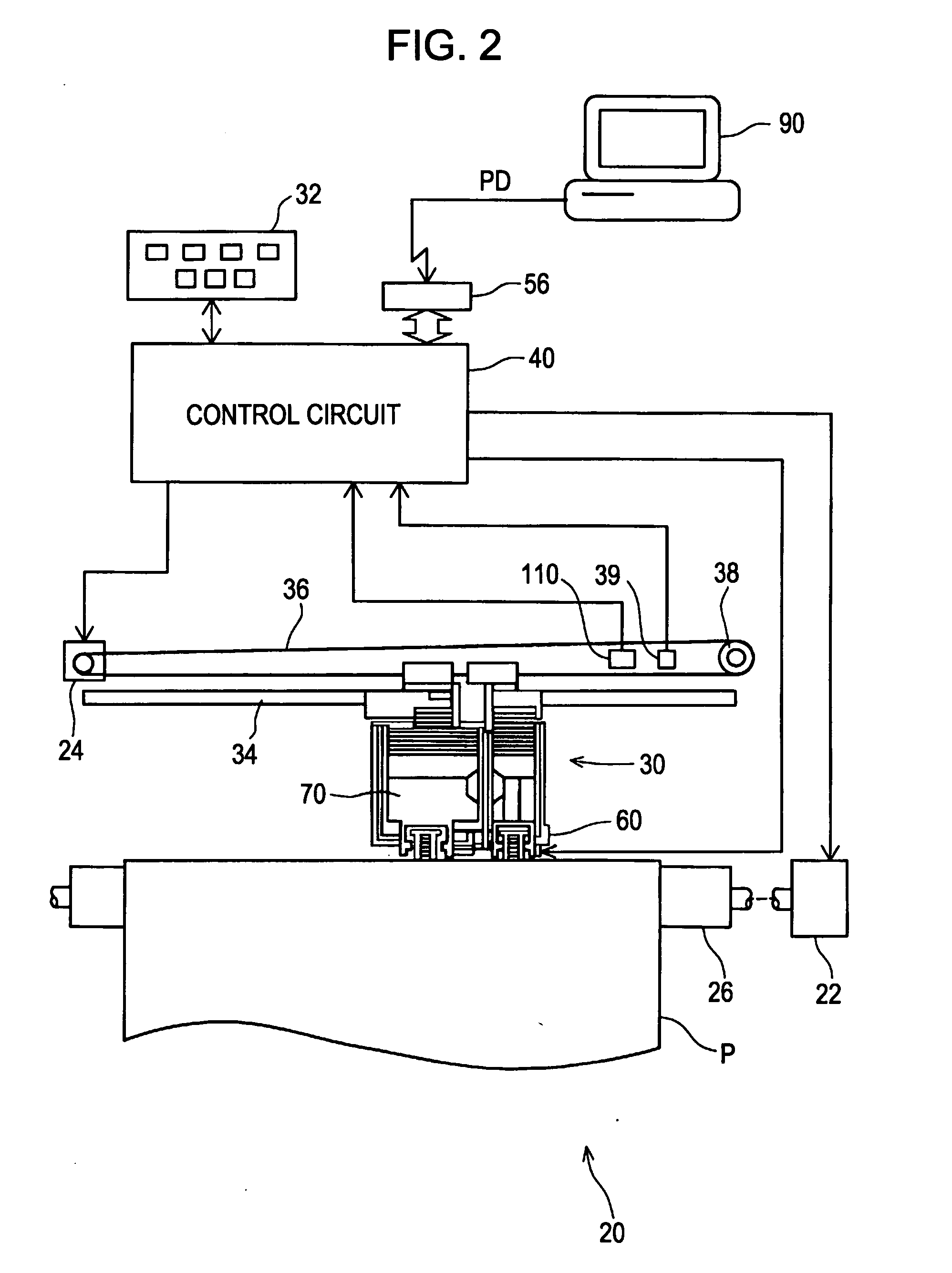
[0028]FIG. 1 is a block diagram illustrating a configuration of a printing system according to a first example of the invention. The printing system includes a computer 90 and a color printer 20. The combination of printer 20 and computer 90 can be called a “liquid ejecting apparatus” in a broad sense. Alternatively, a program, which is installed on the printer 20 and the computer 90 so as to function as a printer driver, may be called the liquid ejecting apparatus in a broad sense. A printer that has a printer driver function may be called the liquid ejecting apparatus.

[0029]In the computer 90, an application program 95 is carried out under a predetermined operating system. The operating system contains a video driver 91 or a printer driver 96 incorporated therein, and the application 95 outputs print data PD to be transmitted to the printer 20 with the aid of such a driver. The application program 95 having a function of image re...

second example

B. Second Example

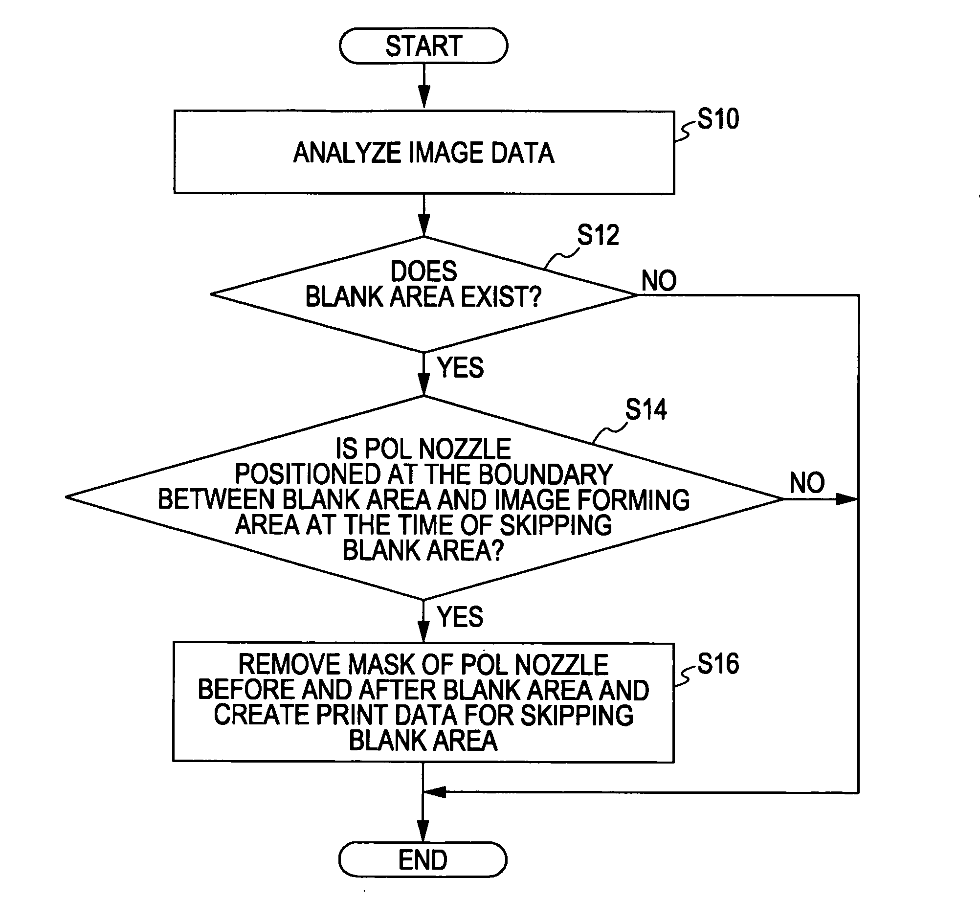
[0071]In second example, transport of a printing paper is controlled so as to position a nozzle, which is not masked, above the boundary between the blank area and the image forming area in cancellation of the POL control at the time of the blank skip control when an image as a printing target includes a blank area.

B1. Printing Process

[0072]FIG. 10 is an explanatory diagram explaining cancellation of POL control at the time of applying a blank skip process according to a second example. In FIG. 10, solid-line circular marks including numerals of the printing head 28 denote nozzles, the numerals denote paths. An image 700 denotes an image represented by image data to be printed, and an image 710 denotes an image obtained by printing the image 700 on a printing paper. Solid-line circular marks including numerals in the image 710 correspond to pixels of the image 710. The numerals in the circular marks denoting the pixels denote paths in which the pixels are formed. Th...


PUM


Abstract

A liquid ejecting apparatus includes: a printing head that ejects liquid to form dots on a recording medium; a head driving section that performs a main scanning for the printing head; a transporting section that performs a sub-scanning for the recording medium; an image forming section that forms an image, a first dot formation area and a second dot formation area; an overlap control section that performs overlap control for intermittently forming dots on the first and second dot formation areas so as to make the second dot formation area overlap with the first dot formation area and fill spaces between the dots intermittently formed on the first dot formation area; and a cancellation section that cancel the overlap control when a blank area exists in an image and a nozzle forming at least one of the first dot formation area and the second dot formation area.

Description

BACKGROUND[0001]1. Technical Field[0002]The present invention relates to a liquid ejecting apparatus that forms an image on a recording medium by ejecting liquid.[0003]2. Related Art[0004]An ink jet type printer (hereinafter, it is referred to as an ink jet printer) has been used as an example of liquid ejecting apparatuses, which forms an image by scanning a printing head having a plurality of nozzles for forming dots in a main scanning direction, ejecting liquid, and transporting a recording medium in a sub-scanning direction intersecting the main scanning direction. Such an inkjet printer, for example, repeatedly forms an area (hereinafter, it is referred to as a band) having a width depending on a length of arrangement of the plurality of nozzles of the printing head, repeatedly transports the recording medium in the sub-scanning direction in accordance with the band width during a single scanning of the printing head, and arranges bands in the sub-scanning direction so as to br...

Claims


Application Information

Patent Timeline
IPC IPC(8): B41J29/38
CPCG06K15/105
Inventor SANTO, AKITOISHIMOTO, BUNJIYUDA, TOMOHIROTANOUE, TAKESHISUDO, NAOKI
Owner SEIKO EPSON CORP
Why Eureka
Try Eureka