Eureka AIR delivers breakthrough ideas for toughest innovation challenges, trusted by R&D personnel around the world.

Optical apparatus including image pick-up device and interchangeable lens with controller for controlling change of aperture

an optical apparatus and controller technology, applied in the field of optical equipment, can solve the problems of excessive limitation of the exposure adjustable range of the aperture stop unit, relative long time taken from an out-of-focus state to an in-focus state, etc., and achieve the effect of preventing image degradation and limiting the exposure adjustable rang

Inactive Publication Date: 2006-01-31
CANON KK
View PDF11 Cites 21 Cited by
  • Summary
  • Abstract
  • Description
  • Claims
  • Application Information

AI Technical Summary

Benefits of technology

The present invention provides a lens or image pickup system that prevents image degradation caused by the diffraction phenomenon, even when using an aperture smaller than the minimum value allowed by the aperture member. This is achieved by a controller that changes the aperture diameter based on information about the image pickup device, such as high-sensitivity image pickup, high-resolution image pickup, or image pickup of a moving picture. The lens or image pickup system can also issue a warning in advance to avoid image degradation, and can adjust the aperture diameter to minimize the impact of the aperture on the exposure range. Overall, the invention allows for optimal image pickup in different image pickup devices and modes.

Problems solved by technology

In this method, a relatively long time is taken from an out-of-focus state to an in-focus state.
However, when the same lens interchangeable from an image pickup apparatus can be mounted on different image pickup apparatuses with image pickup devices, such as a video camera, a digital still camera with a higher-resolution CCD, and a digital still camera with higher sensitivity, or when the image pickup device can be interchanged from the image pickup apparatus in accordance with the intended use, the following problems arise unless the F value as a limit aperture diameter is set changeable in accordance with the CCD form (e.g., the numerical value of the pixel pitch).a) The image degrades due to the diffraction phenomenon depending on a selected CCD.b) The exposure adjustable range by the aperture stop unit is excessively limited depending on a selected CCD.

Method used


Image

  • Optical apparatus including image pick-up device and interchangeable lens with controller for controlling change of aperture
  • Optical apparatus including image pick-up device and interchangeable lens with controller for controlling change of aperture
  • Optical apparatus including image pick-up device and interchangeable lens with controller for controlling change of aperture

Examples


first embodiment

(First Embodiment)

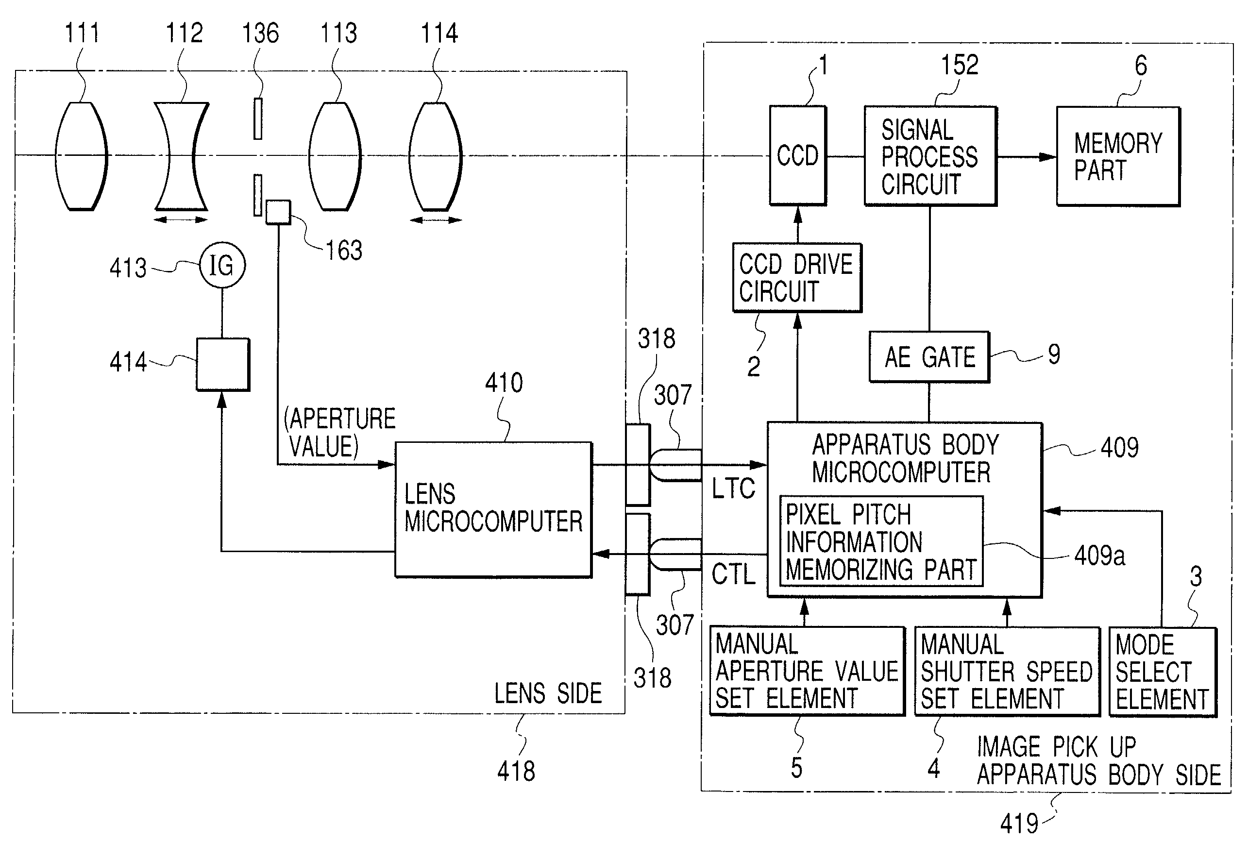
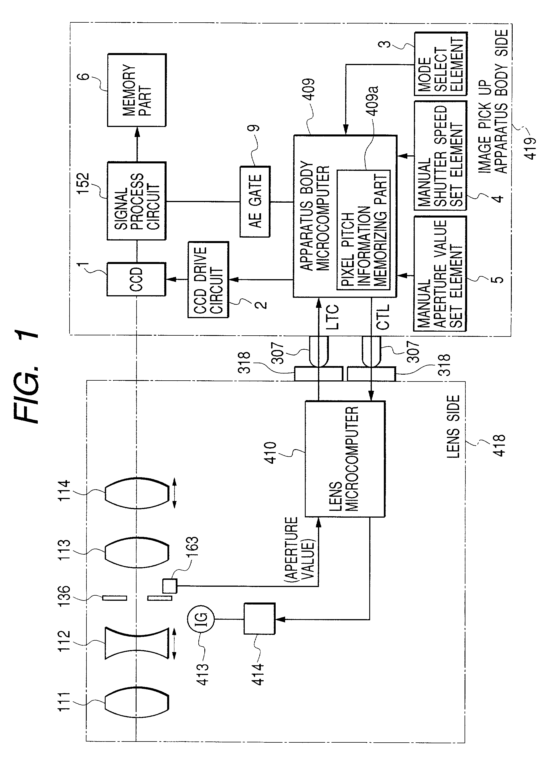
[0131]FIG. 1 is a block diagram showing the arrangement of the main part of a lens-interchangeable image pickup system according to the first embodiment of the present invention. The same reference numerals as in FIG. 12 denote parts having the same functions.

[0132]In FIG. 1, the image pickup apparatus body side comprises a CCD 1 serving as an image pickup device, and a CCD drive circuit 2 for driving the CCD 1. A mode select element 3 is used to select an image pickup mode such as an auto mode, portrait mode, aperture priority mode, and shutter priority mode. A manual shutter speed set element 4 is used to select an arbitrary shutter speed. A manual aperture value set element 5 is used to set an arbitrary aperture value. The image pickup apparatus also comprises an AE gate 9.

[0133]The lens side comprises a fixed front lens 111, a variator lens 112 which moves along the optical axis to change the magnification, an aperture stop unit 136 serving as a light quantity ...

second embodiment

(Second Embodiment)

[0145]The first embodiment shown in FIG. 1 has exemplified an image pickup system as a combination of an image pickup apparatus body and interchangeable lens. As shown in FIG. 3, the second embodiment of the present invention will exemplify an image pickup system (optical apparatus) as a combination of an image pickup unit 502 including a CCD 1 serving as an image pickup device, a signal process circuit 152, a CCD drive (driver) circuit 2, and a CCD block microcomputer 7, and a main body unit 501 including lenses 111 to 114, a microcomputer 8, and a memory part 6. That is, the second embodiment provides an image pickup system (optical apparatus) constituted by combining any one of image pickup units 502 having different forms of image pickup devices to the main body unit 501.

[0146]In FIG. 3, the CCD block microcomputer 7 stores information concerning the pixel pitch of the CCD 1 in a memory part (not shown) such as a memory. The CCD block microcomputer 7 transmits...

third embodiment

(Third Embodiment)

[0147]An image pickup system (optical apparatus) according to the third embodiment of the present invention will be described. Either of the image pickup system arrangements in FIGS. 1 and 3 can be applied, and the third embodiment will be exemplified using the arrangement of FIG. 1.

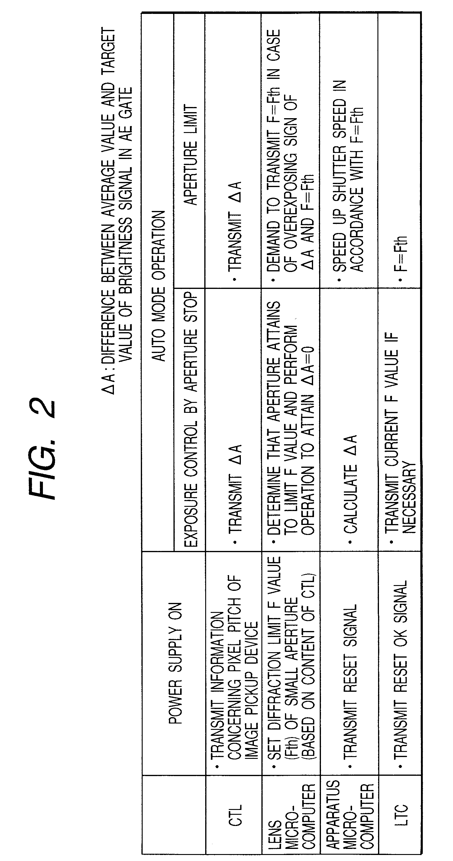
[0148]If the image pickup mode is set to an auto mode or portrait mode by a mode select element 3 in an image pickup system having the arrangement of FIG. 1, settings of the shutter speed and aperture value by set elements 4 and 5 are ignored or the shutter speed and aperture value cannot be set.

[0149]This operation is summarized in the item “AUTO MODE OPERATION” in FIG. 2.

[0150]In a situation where the exposure can be controlled in a general aperture stop, an apparatus microcomputer 409 calculates a difference ΔA between the average value and target value of a brightness signal in an AE gate 9. For example, a positive difference ΔA means overexposure, and a negative difference ΔA means...


PUM


Abstract

This invention discloses an optical apparatus including an image pickup optical unit, a light quantity adjustment unit inserted in the optical axis of the image pickup optical unit, the light quantity adjustment unit changing the aperture diameter to change the light quantity, and a controller for controlling a change of the aperture diameter by the light quantity adjustment unit. The controller changes the set value for the minimum aperture diameter of the aperture diameter of the light quantity adjustment unit in accordance with the form of the image pickup device of the image pickup apparatus on which the lens apparatus is mounted.

Description

BACKGROUND OF THE INVENTION[0001]1. Field of the Invention[0002]The present invention relates to an optical apparatus and, more particularly, to an optical apparatus including a plurality of image pickup apparatuses using different forms of image pickup devices, an interchangeable lens applied to these image pickup apparatuses, and an aperture stop unit for the interchangeable lens.[0003]2. Related Background Art(1) Conventional Description of General Lens for Video Camera[0004]A conventional most-well-known zoom lens for a video camera is made up of four lens units: a fixed positive lens unit, movable negative lens unit, fixed positive lens unit, and movable positive lens unit sequentially from the object side. In addition to this arrangement, zoom lenses with various lens arrangements are also known.[0005]FIGS. 6A and 6B are sectional views showing the barrel structure of a zoom lens having the most popular four-lens-unit arrangement described above. FIG. 6B is a sectional view ta...

Claims


Application Information

Patent Timeline
Patent Type & Authority Patents(United States)
IPC IPC(8): H04N5/225H04N5/238G03B7/095G02B7/02G02B7/10G03B9/02G03B17/14G03B17/18G03B17/20H04N23/75
CPCH04N5/238H04N5/23209H04N23/663H04N23/75
Inventor KANEDA, NAOYA
Owner CANON KK
Why Eureka
Eureka Blog
Learn More