
Absorbent material and solar panel using such a material

a technology of absorbent materials and solar panels, applied in the direction of superimposed coating processes, instruments, optical elements, etc., can solve the problems of reducing the stagnation temperature of the material, the production of panels with a layer having a variable surface morphology is rather complex on an industrial scale, and the degradation of the heat transfer fluid is urgent,

Active Publication Date: 2017-06-06
VIESSMANN FAULQUEMONT +2
View PDF4 Cites 8 Cited by
  • Summary
  • Abstract
  • Description
  • Claims
  • Application Information

AI Technical Summary

Benefits of technology

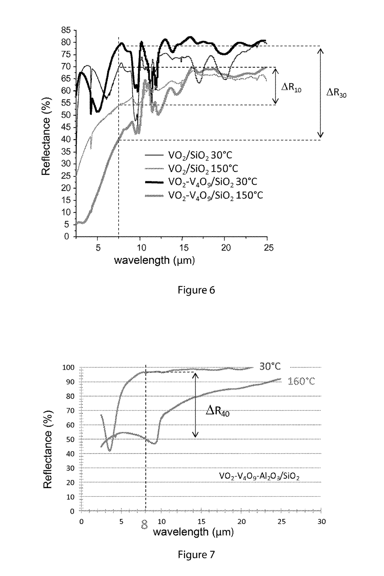
The invention relates to a multilayer material with a selective layer that has increased absorption of infrared radiation, compared to a layer of pure VO2 of the same thickness. This is achieved by increasing the path of infrared radiation in the selective layer. The multilayer material also has a higher infrared emissivity than a thermal solar panel using pure VO2, which results in a lower maximum operating temperature. An optional antireflection layer can be added to the selective layer to further increase absorbance, but it should have a thickness of between 10 and 150 nm to maintain the material's properties in the infrared range.

Problems solved by technology

Such a high stagnation temperature results in rapid degradation of the heat transfer fluid which must be renewed frequently; such stagnation temperature also requires the use of high-performance building material for the production of the panel, and the setting up of hydraulic systems to manage overpressures (expansion tank).
In practice, the production of panels provided with a layer having a variable surface morphology is rather complex on an industrial scale.
And experience shows that the use of a single layer of VO2 alone, without a layer of a material having a variable surface morphology, reduces the stagnation temperature of the material, but not sufficiently to limit degradation of a heat transfer fluid flowing in the vicinity of the panel or to enable the use of less expensive materials for producing the support and the frame of the panel.

Method used


Image

  • Absorbent material and solar panel using such a material
  • Absorbent material and solar panel using such a material
  • Absorbent material and solar panel using such a material

Examples


Embodiment Construction

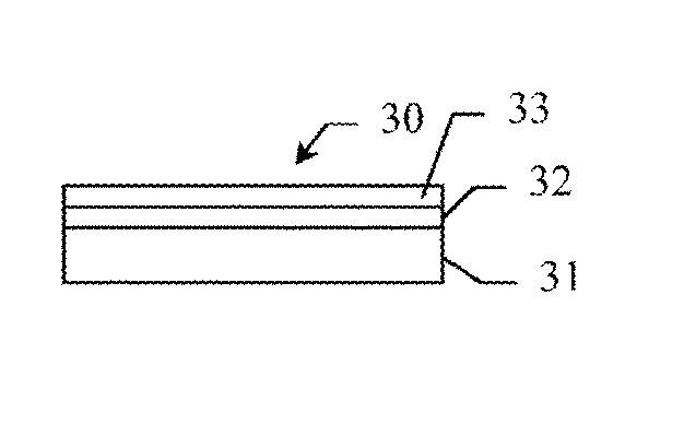
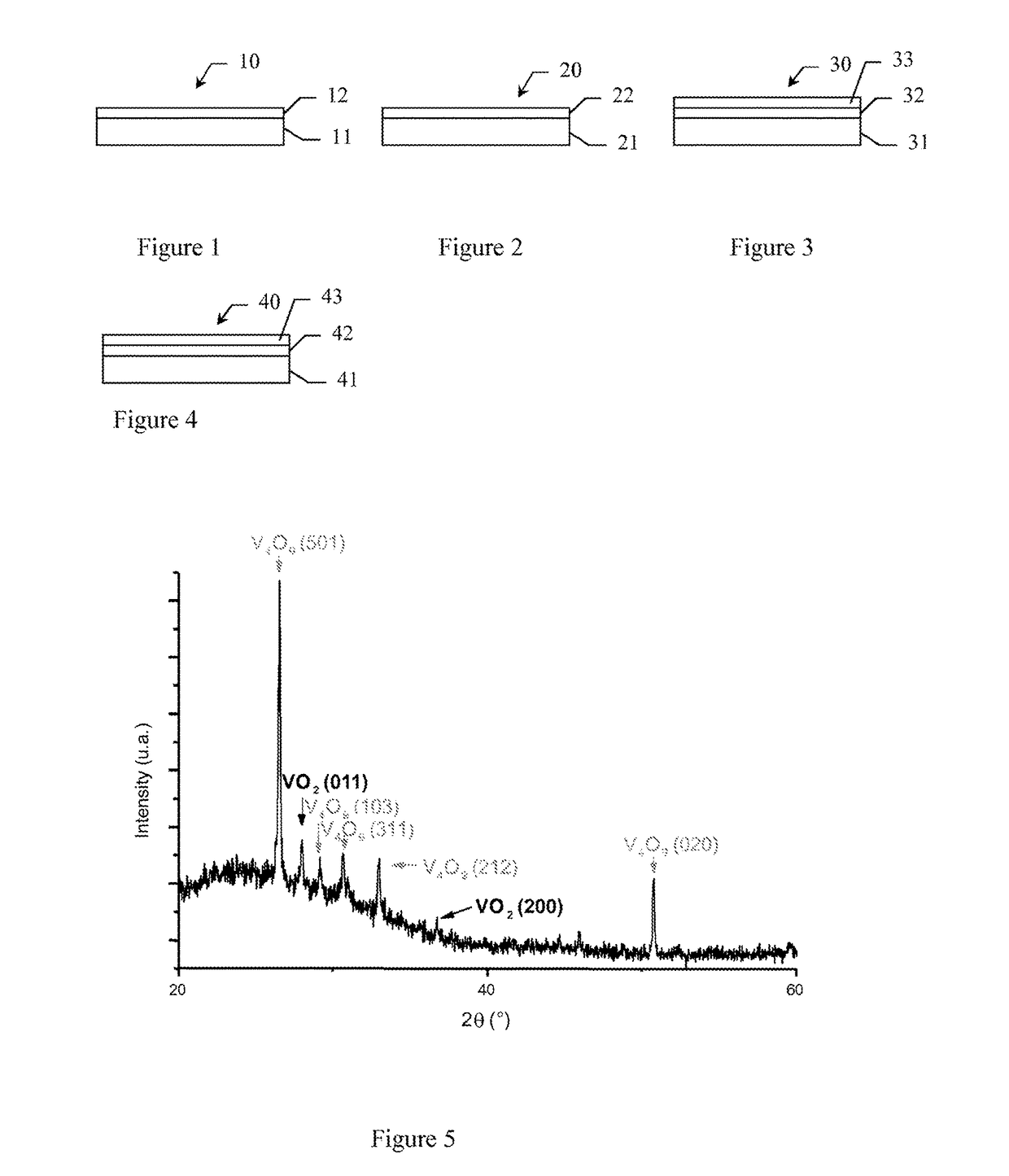
[0018]The invention provides a novel multilayer material having a low stagnation temperature, and a solar panel comprising such a multilayer material. More specifically, the invention provides a novel multilayer material comprising at least:[0019]a support having a reflectance R higher than 80% for radiations of wavelengths higher than 5 μm,[0020]a selective layer comprising a combination of Vanadium oxides VO2 and VnO2n+ / −1, with n>1, said selective layer having a solar absorbance higher than 75% for radiations of wavelengths comprised between 0.4 and 2.5 μm regardless of the temperature T and having, for radiations having wavelengths comprised between 6 and 10 μm, a transmittance Tr such that:[0021]Tr>85% for T[0022]20%=Tc.

[0023]Tests show that a layer of pure VO2 has an infrared (6-10 μm) transmittance at T>Tc lower than 10% and is thus virtually opaque. For T>Tc, for infrared radiations (6-10 μm), the selective layer according to the invention is characterized by a partial infra...


PUM

PropertyMeasurementUnit
reflectivityaaaaaaaaaa
transmittanceaaaaaaaaaa
thicknessaaaaaaaaaa

Abstract

The invention concerns a multilayer material comprising at least:a support having a reflectance R higher than 80% for radiations of wavelengths higher than 5 μm,a selective layer comprising a combination of Vanadium oxides VO2 and VO2O2n+ / −1, with n>1, said selective layer having an absorbance higher than 75% for radiations of wavelengths comprised between 0.4 and 2.5 μm, regardless of the temperature T, and having, for radiations of wavelengths comprised between 6 and 10 μm, a transmittance Tr such that:Tr>85% for T<Tc, a critical temperature,20%≦Tr≦50% for T>Tc.Application to the production of thermal solar panels having a low stagnation temperature and high performance.

Description

DEFINITIONS[0001]Any body at temperature T subjected to an electromagnetic radiation having a wavelength λ, and an incident energy E(λ, T) transmits, absorbs or reflects a portion thereof according to the following equation (1):E(λ,T)=Et(λ,T)+Ea(λ,T)+Er(λ,T)=τ·E(λ,T)+α·E(λ,T)+ρ·E(λ,T)   (1)where τ, α, ρ are, respectively, the transmission, absorption, and reflection coefficients of the material. These coefficients are also called transmittance, absorbance and reflectance. The principle of conservation of the total incident energy makes it possible to relate these coefficients with one another according to the equation: τ+α+ρ=1. In the case where the body under consideration is opaque to incident radiation (τ=0), its absorbance is complementary to its reflectance (α=1−ρ).[0002]The emissivity of a material corresponds to its ability to emit radiation as compared to a black body, which absorbs all the energy it receives and radiates all the energy it absorbs to maintain its thermal equ...

Claims


Application Information

Patent Timeline
Patent Type & Authority Patents(United States)
IPC IPC(8): G02B5/20G02B1/11G02B5/08F24J2/46C23C14/06G02F1/15G02F1/01C23C28/04C23C14/08F24J2/48
CPCF24J2/487C23C14/0641C23C14/083C23C28/042F24J2/4652F24J2/485G02B1/11G02B5/0808G02B5/208G02F1/0126G02F1/15F24J2002/4683Y02E10/40F24S70/225F24S70/30F24S2080/01
Inventor MERCS, DAVIDCAPON, FABIENCORVISIER, ALAN
Owner VIESSMANN FAULQUEMONT
Learn More