
Minute current crimping terminal and minute current wire harness

a technology of crimping terminal and wire harness, which is applied in the direction of insulated conductors, connection contact material, cables, etc., can solve the problems of rapid copper crimping terminal, and corrosion of core wire and crimping terminals, so as to reduce the temperature increase, and the configuration is simple

Active Publication Date: 2017-05-30
YAZAKI CORP
View PDF18 Cites 2 Cited by
  • Summary
  • Abstract
  • Description
  • Claims
  • Application Information

AI Technical Summary

Benefits of technology

The present invention provides a minute current crimping terminal and wire harness that have simple configurations and are hard to corrode even after long periods of use. The terminal is designed to prevent corrosion of the core wire and crimping terminals, even in severe environments like sea breeze, high temperature, and high humidity. Moreover, the invention also reduces temperature increase and electrical resistance increase due to the temperature increase of a minute current flowing through the terminal. The wire harness includes a wire barrel portion connected to a core wire and made of corrosion-resistant materials like iron or iron alloy, and a first layer and second layer of materials to remove passive film and increase corrosion resistance and lubricity. Overall, the invention provides a solution for protecting sensitive components from corrosion in vehicles and other environments that promote the use of copper crimping terminals.

Problems solved by technology

When a core wire including aluminum or aluminum alloy is connected to this crimping terminal, elution of aluminum is promoted, and corrosion of the core wire and the crimping terminal progresses rapidly, due to the potential difference between the aluminum included in the core wire and the copper included in the base material.
However, a copper crimping terminal has a problem of having the possibility that corrosion of the core wire and crimping terminals progresses rapidly by many years of use of the vehicle (vehicle where a copper crimping terminal is used) under severe use environment such as exposure to the sea breeze, and high temperature and high humidity, even when tin plating is provided on the surface.
As a result, in a copper crimping terminal to which a core wire including aluminum or the like is connected, the elution of aluminum and the elution of tin are promoted by the potential difference between aluminum included in the core wire and copper included in the base material, and corrosion of the core wire and the crimping terminal progresses rapidly.
In addition, if a normal current flows through the copper crimping terminal where corrosion has occurred in this way and the terminal is used, there is a possibility that the terminal generates heat and that the electrical resistance value rises.

Method used


Image

  • Minute current crimping terminal and minute current wire harness
  • Minute current crimping terminal and minute current wire harness
  • Minute current crimping terminal and minute current wire harness

Examples


first embodiment

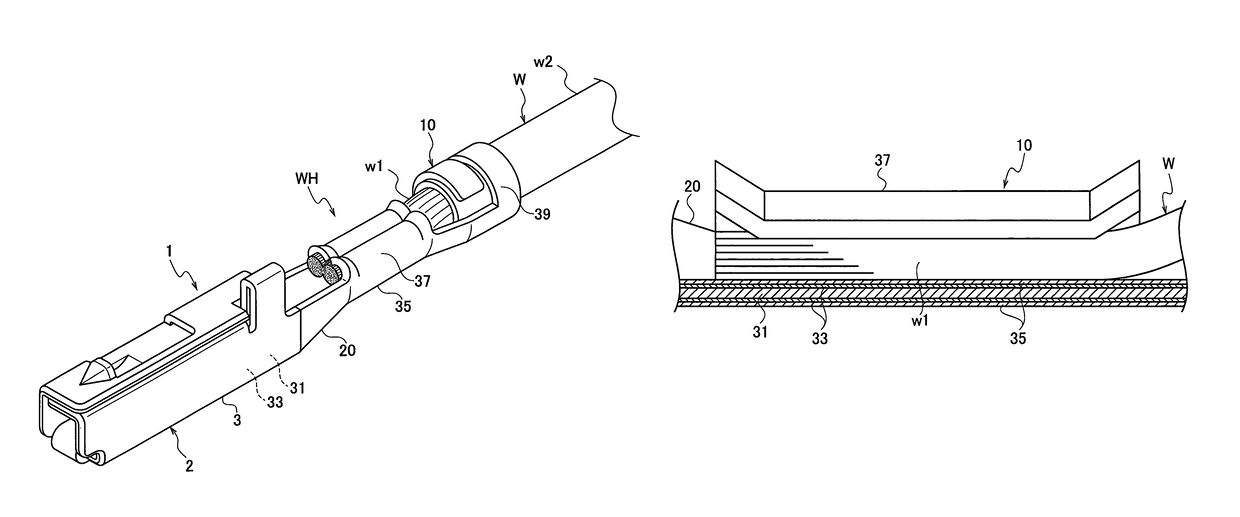
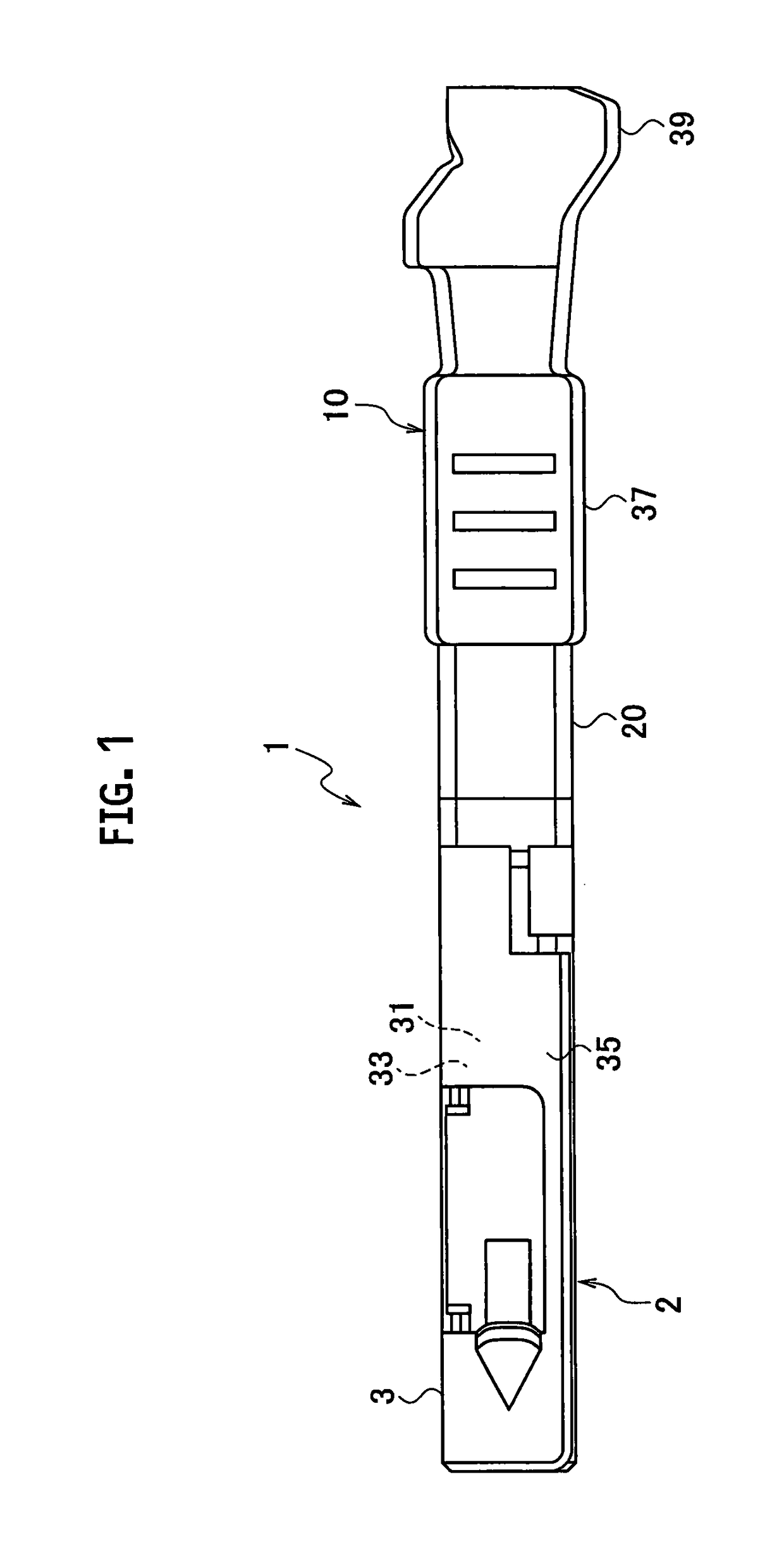
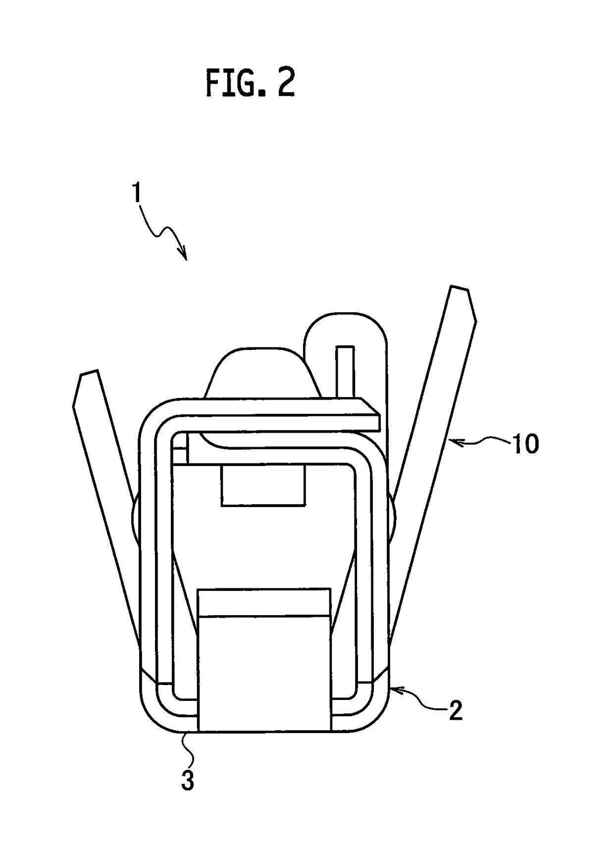
[0036]A minute current crimping terminal 1 according to a first embodiment is, as shown in FIGS. 3 and 4, is connected to wire (for example, minute current wire) W to be used, and a core wire (conductor) w1 of the wire W includes, for example, aluminum or aluminum alloy. In addition, the current flowing through the core wire w1 and the minute current crimping terminal 1 connected to the core wire w1 is lower than a normal current. The wire W where minute current crimping terminal (crimping terminal for electrical signal transmission) 1 is installed (connected) becomes minute current wire harness (for example, wire harness for transmitting a signal in a vehicle) WH. The minute current wire harness WH is, for example, connected to a minute current circuit to be used.

[0037]In addition, a base material 31 (see FIG. 5) provided with a first layer 33 and a second layer 35 on the surface, made of conductive metal material, is punched into a predetermined shape by press working, and the con...

second embodiment

[0061]A crimping terminal 101 according to a second embodiment, the crimping terminal 101 includes: a wire barrel portion 137 to which a core wire w3 including aluminum or aluminum alloy is connected; a material containing iron or iron alloy with corrosion resistance as base material 131; at least a first layer 133 provided on a surface of a part of the base material 131 constituting the wire barrel portion 137; and at least a second layer 135 provided on a surface of the first layer 133, wherein the first layer 133 includes a material to remove a passive film present on a surface of the base material 131, the second layer 135 includes a material capable of increasing corrosion resistance and lubricity, and stabilizing a value of electrical resistance, the wire barrel portion 137 is configured to include a bottom surface portion 111 and a pair of conductor crimping portions 112A and 112B extending laterally from both sides of the bottom surface portion 111, and recesses 114 are prov...


PUM

PropertyMeasurementUnit
currentaaaaaaaaaa
thicknessaaaaaaaaaa
thicknessaaaaaaaaaa

Abstract

A minute current crimping terminal (1) includes a wire barrel portion (37) connected to a core wire including any one of aluminum and aluminum alloy, a current flowing through the core wire being lower than a normal current. The wire barrel portion (37) includes a base material (31) including any one of iron and iron alloy with corrosion resistance, at least a first layer (33) provided on a surface of a part of the base material (31) configuring the wire barrel portion (37), and at least a second layer (35) provided on a surface of the first layer (33), wherein the first layer (33) includes a material to remove a passive film present on a surface of the base material (31), and the second layer (35) includes a material capable of increasing corrosion resistance and lubricity, and stabilizing a value of electrical resistance.

Description

CROSS REFERENCE TO RELATED APPLICATIONS[0001]This application claims the priority of Japanese Patent Application No. 2014-103639, filed on May 19, 2014, and Japanese Patent Application No. 2014-103566, filed on May 19, 2014, the entire content of which are incorporated herein by reference.BACKGROUND[0002]Technical Field[0003]The present invention relates to a minute current crimping terminal and a minute current wire harness.[0004]Related Art[0005]Conventionally, a crimping terminal (copper crimping terminal) including a base material containing copper or copper alloy has been known. When a core wire including aluminum or aluminum alloy is connected to this crimping terminal, elution of aluminum is promoted, and corrosion of the core wire and the crimping terminal progresses rapidly, due to the potential difference between the aluminum included in the core wire and the copper included in the base material.[0006]Therefore, conventionally, a crimping terminal (copper crimping terminal...

Claims


Application Information

Patent Timeline
Patent Type & Authority Patents(United States)
IPC IPC(8): H01R4/20H01B7/28H01R13/03H01R4/62H01R4/26H01R43/00H01R4/18H01R13/11
CPCH01R4/184H01B7/2806H01R4/185H01R4/26H01R4/62H01R13/03H01R43/00H01R4/188H01R13/11Y10T29/4921
Inventor TAKAHASHI, TAKAKAZU
Owner YAZAKI CORP
Learn More