
Sheet-metal flat seal layer and method for the production thereof

a technology of flat sealing and sheet metal, applied in the direction of mechanical equipment, transportation and packaging, machines/engines, etc., can solve the problems of high material cost, achieve the effect of minimizing the tensile for

Active Publication Date: 2017-05-30
ELRINGKLINGER AG
View PDF12 Cites 1 Cited by
  • Summary
  • Abstract
  • Description
  • Claims
  • Application Information

AI Technical Summary

Benefits of technology

[0008]As a result, significantly less material is needed for manufacturing the flat seal layer with a pre-defined final outer contour, specifically only the metal sheet required for manufacturing the smaller blank. In particular, a flat seal layer can be made so that during the manufacturing of the installation-ready flat seal layer or flat seal with its pre-determined final outer contour, no further appreciable stamping waste is generated, specifically in addition to the stamping waste which is inevitable during the manufacturing of the blank and the openings such as medium openings and screw holes.
[0039]With regard both to minimizing the tensile forces required for stretching the sheet-metal layer and also for achieving the greatest possible effect through the stretching, it is particularly advantageous if the stretched sub-region of the seal layer is formed by an expanded metal region of the sheet-metal layer.

Problems solved by technology

Particularly for large metallic flat seals which are subject to relatively high and high operating temperatures, such as elongate exhaust manifold seals, intake manifold seals and cylinder head seals for multiple-cylinder internal combustion engines, the material costs are usually a decisive factor since expensive spring steels and / or steels able to withstand high temperatures must be used for these flat seals and, in this regard, it should be noted that the material costs are high even if steels initially not having resilient properties are processed and are then given resilient properties by means of a heat treatment.

Method used


Image

  • Sheet-metal flat seal layer and method for the production thereof
  • Sheet-metal flat seal layer and method for the production thereof
  • Sheet-metal flat seal layer and method for the production thereof

Examples


Embodiment Construction

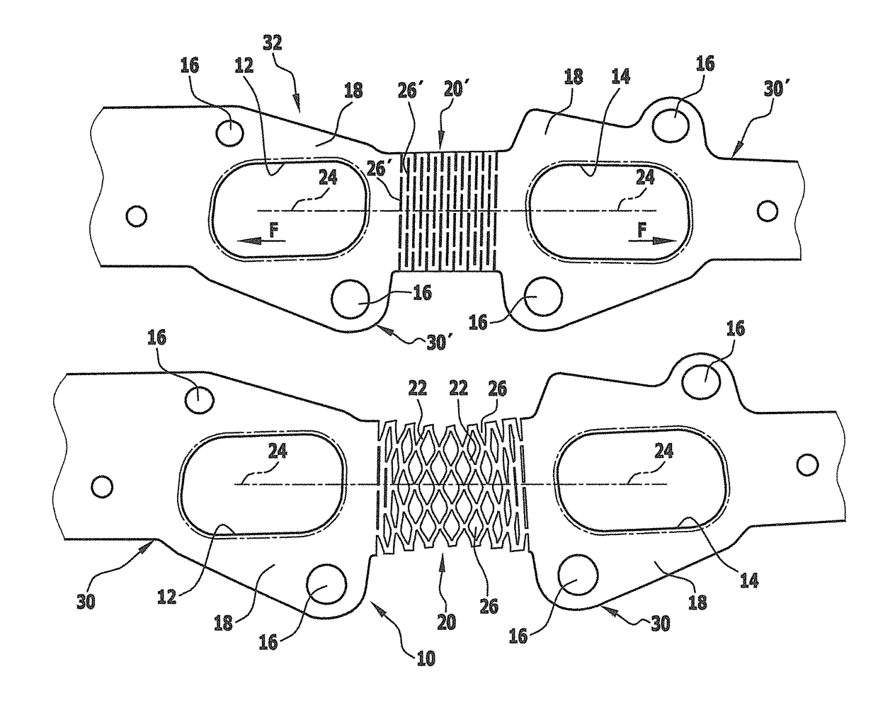
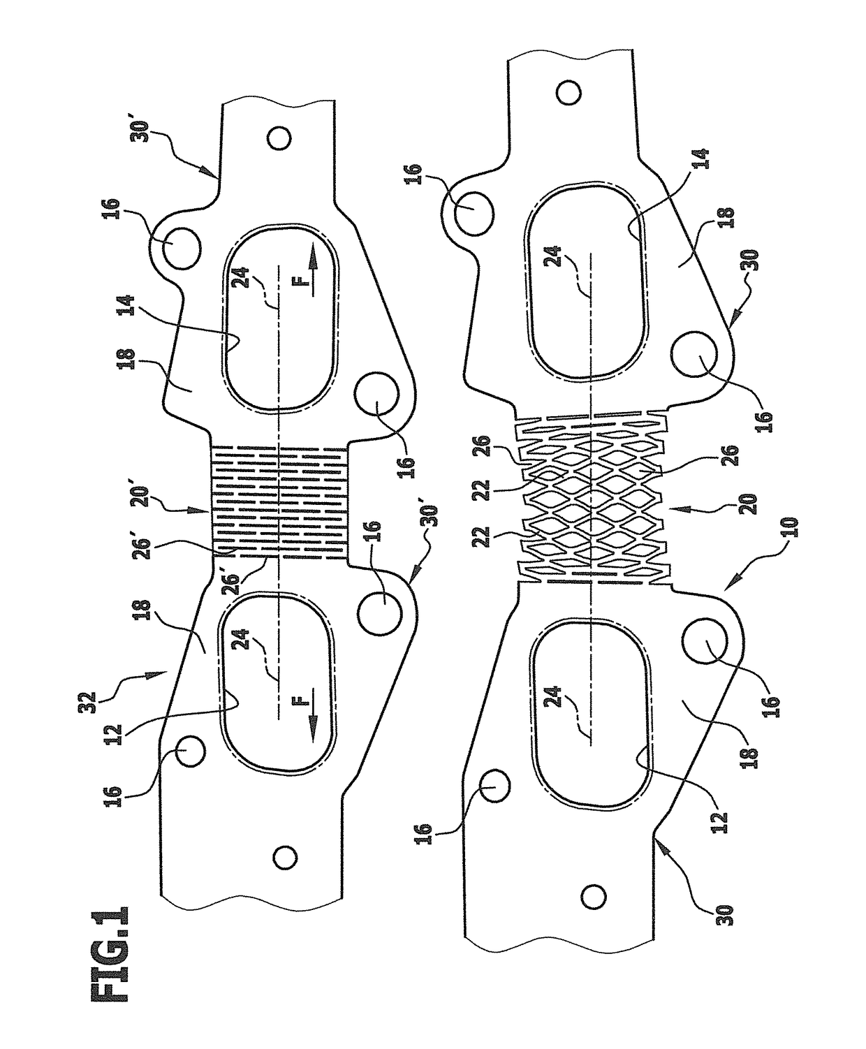
[0048]FIG. 1 shows, at the bottom, a part of a sheet-metal flat seal layer 10 which can be one seal layer of a multiple-layer flat seal or the one layer of a single-layer seal, specifically in the case of the embodiment shown, a manifold seal, in particular an exhaust manifold seal for installation between a cylinder head and an exhaust manifold of a multiple-cylinder internal combustion engine.

[0049]The seal layer 10 has a plurality of gas through openings, of which FIG. 1 shows only the two gas through openings 12 and 14, but otherwise some holes, for example, a plurality of screw holes 16 for penetration by mounting screws with the aid of which the flat seal is clamped between components, in the present case between a cylinder head and an exhaust manifold.

[0050]The part of the single-piece seal layer 10 shown in FIG. 1 at the bottom comprises two first layer regions 18 with the gas through openings 12, 14 and a second layer region 20 which is arranged between these first layer re...


PUM

PropertyMeasurementUnit
angleaaaaaaaaaa
angleaaaaaaaaaa
angleaaaaaaaaaa

Abstract

A flat seal having at least one single-piece sheet-metal seal layer is provided, which has at least one first layer region provided with at least one medium through opening and, outside the first layer region, at least one second layer region and, with the flat seal installation-ready, has a pre-determined outer contour, wherein the flat seal for the medium through opening has a medium-sealing device. In order to reduce the material requirement for manufacturing the seal layer, the seal layer is configured so that at least one sub-region of the second layer lying outside the medium-sealing device region of the seal layer is formed by a region of the sheet-metal layer that is stretched in the layer plane to achieve the pre-determined outer contour.

Description

CROSS-REFERENCE TO RELATED APPLICATIONS[0001]The present application is a continuation of international application number PCT / EP2014 / 050362, filed on Jan. 10, 2014, which claims priority to German patent application number 10 2013 100 612.4, filed on Jan. 22, 2013, the entire specification of both being incorporated herein by reference.BACKGROUND OF THE INVENTION[0002]The invention relates to a sheet-metal flat seal layer and a single-layer or multiple-layer flat seal which has a sheet-metal layer of this type, a blank of a sheet-metal layer of this type and a method for the production of a flat seal layer of this type.[0003]Metallic flat seals often consist of a single-piece sheet-metal layer or a plurality of substantially congruent sheet-metal layers or one sheet-metal layer functioning as a carrier layer on which sheet-metal coatings are arranged on one or both sides. Typically, the one sheet-metal layer or at least one of the sheet-metal layers extends over the whole so-called...

Claims


Application Information

Patent Timeline
Patent Type & Authority Patents(United States)
IPC IPC(8): F16J15/08B21D35/00F16J15/02F16J15/06F01N13/18
CPCF16J15/0818B21D35/001F01N13/1827F16J15/024F16J15/064F16J2015/085F16J2015/0868Y10T428/12229
Inventor KULLEN, WILHELM
Owner ELRINGKLINGER AG
Learn More