Self-driven synchronous rectifier circuit

a synchronous rectifier and self-driven technology, applied in the field of power converters, can solve the problems of increasing the complexity of the transformer design, the source of power loss, and the power loss incurred in the circui

Active Publication Date: 2017-05-23
FLEXTRONICS AP LLC
View PDF9 Cites 7 Cited by
  • Summary
  • Abstract
  • Description
  • Claims
  • Application Information

AI Technical Summary

Benefits of technology

[0014]A power converter includes a self-driven circuit for appropriately turning ON and OFF a synchronous rectifier during the operating cycle of the power converter. Without the use of a smart controller coupled to the synchronous rectifier, the self-driven circuit turns ON the synchronous rectifier during the positive cycle of the power converter when the main switch is turned OFF, and the self-driven circuit turns OFF the synchronous rectifier during the negative cycle of the power converter when the main switch is turned ON. Unlike conventional self-driven circuits that include an auxiliary secondary winding for driving a synchronous rectifier, the self-driving circuitry of the present application does not include an auxiliary secondary winding.

Problems solved by technology

However, in the flyback converter, the primary and secondary windings of the transformer do not carry current simultaneously.
A drawback of the flyback type converter, as with all power converters, is power loss incurred within the circuit.
This source of power loss is not limited to flyback type converters, but to any power converter having a secondary side diode that carries secondary side current.
An issue associated with using the synchronous rectifier is how to efficiently and economically turn ON the transistor Q2.
However, introduction of the additional secondary winding S2 increases the complexity of the transformer design.
A fundamental issue with a MOSFET is that it is not strictly a uni-directional current element when turned ON.
A series configuration reduces circuit complexity but does not completely alleviate the increased complexity of the transformer due to the additional secondary winding.
Although effective, such a configuration needs current build up to drive the synchronous rectifier, which results in a delay during turn ON.
Additional circuit complexity is also needed to properly time turning ON the synchronous rectifier.

Method used


Image

  • Self-driven synchronous rectifier circuit
  • Self-driven synchronous rectifier circuit
  • Self-driven synchronous rectifier circuit

Examples


Embodiment Construction

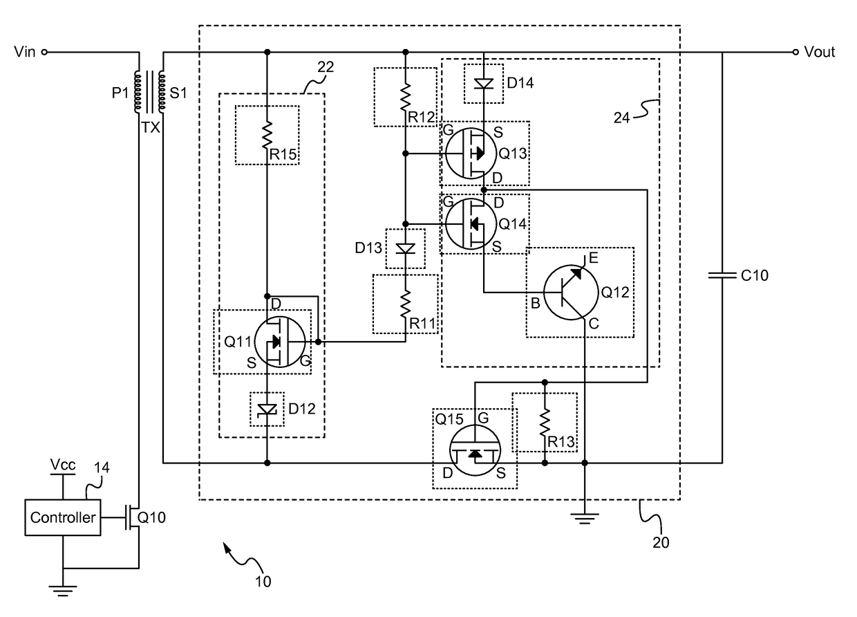
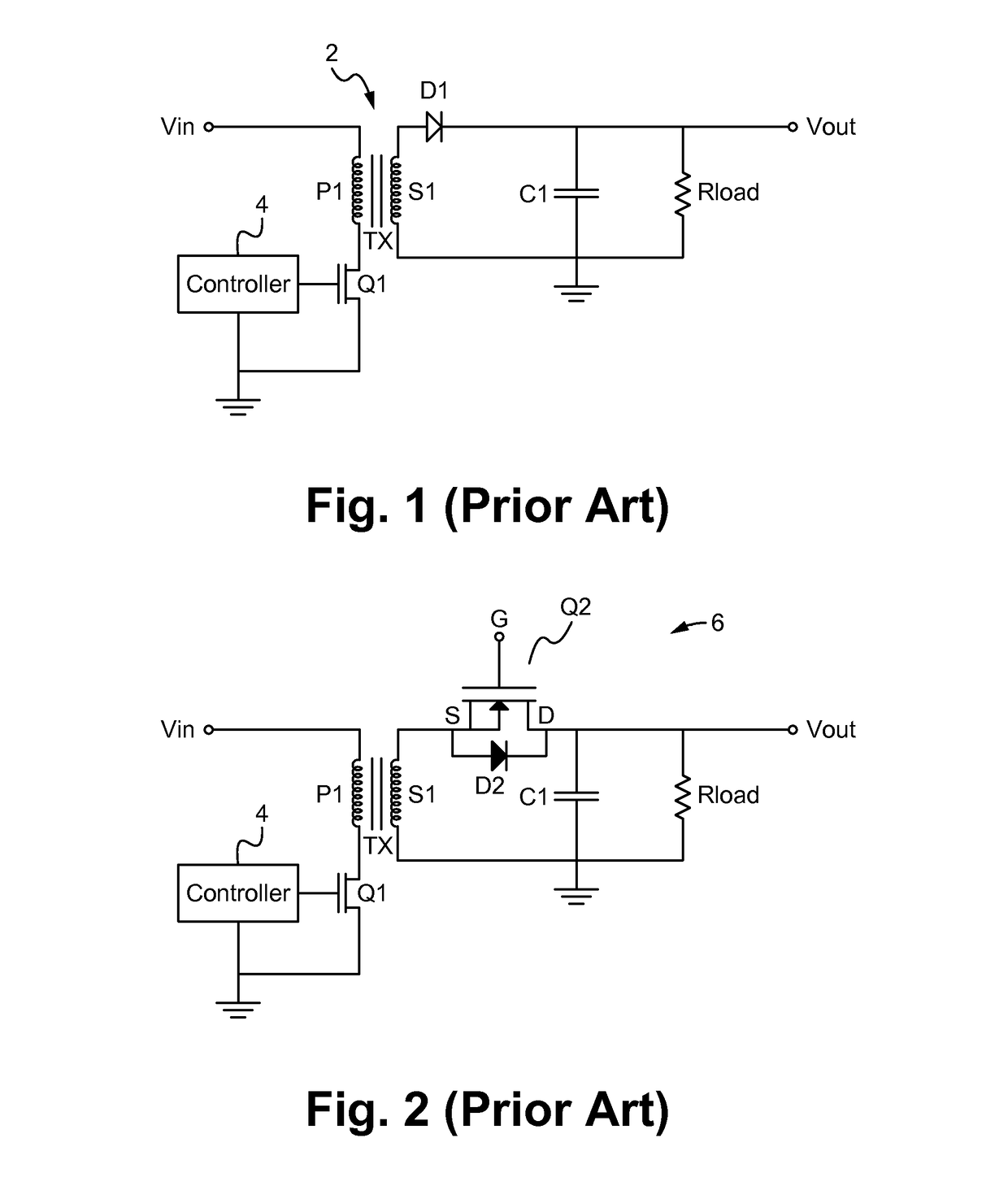
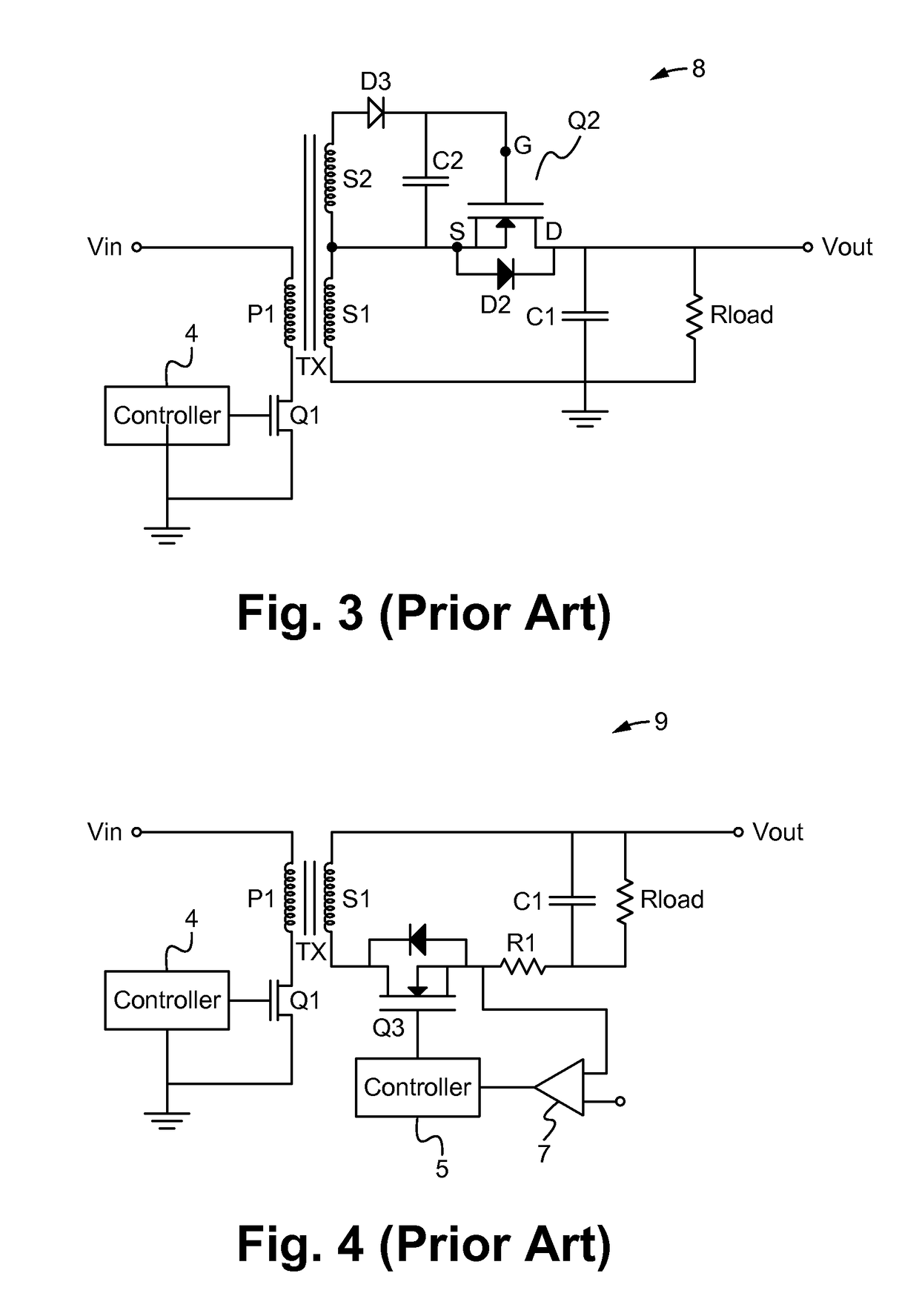
[0025]Embodiments of the present application are directed to a power converter. Those of ordinary skill in the art will realize that the following detailed description of the power converter is illustrative only and is not intended to be in any way limiting. Other embodiments of the power converter will readily suggest themselves to such skilled persons having the benefit of this disclosure.

[0026]Reference will now be made in detail to implementations of the power converter as illustrated in the accompanying drawings. The same reference indicators will be used throughout the drawings and the following detailed description to refer to the same or like parts. In the interest of clarity, not all of the routine features of the implementations described herein are shown and described. It will, of course, be appreciated that in the development of any such actual implementation, numerous implementation-specific decisions must be made in order to achieve the developer's specific goals, such...


PUM


Abstract

A power converter includes a self-driven circuit for appropriately turning ON and OFF a synchronous rectifier during the operating cycle of the power converter. Without the use of a smart controller coupled to the synchronous rectifier, the self-driven circuit turns ON the synchronous rectifier during the positive cycle of the power converter when the main switch is turned OFF, and the self-driven circuit turns OFF the synchronous rectifier during the negative cycle of the power converter when the main switch is turned ON. Unlike conventional self-driven circuits that include an auxiliary secondary winding for driving a synchronous rectifier, the self-driving circuitry of the present application does not include an auxiliary secondary winding.

Description

RELATED APPLICATIONS[0001]This Patent Application claims priority under 35 U.S.C. 119(e) of the U.S. Provisional Application, Ser. No. 62 / 035,244, filed Aug. 8, 2014, and entitled “ADAPTIVE SYNCHRONOUS RECTIFIER CIRCUIT”. This application incorporates U.S. Provisional Application, Ser. No. 62 / 035,244 in its entirety by reference.FIELD OF THE INVENTION[0002]The present invention is generally directed to the field of power converters. More specifically, the present invention is directed to a power converter having an adaptive synchronous rectifier circuit.BACKGROUND OF THE INVENTION[0003]In many applications a power converter is required to provide an output voltage within a predetermined range formed from an output voltage source having a different voltage level. One very common type of power converter is a flyback type voltage converter.[0004]FIG. 1 illustrates a conventional flyback type voltage converter. The converter 2 includes a transistor Q1, a controller 4, a transformer TX, ...

Claims


Application Information

Patent Timeline
Patent Type & Authority Patents(United States)
IPC IPC(8): H02M3/335
CPCH02M3/33592Y02B70/10
Inventor TELEFUS, MARKYEO, PETER RAMOSSHARIFIPOUR, BAHMAN
Owner FLEXTRONICS AP LLC
Why Eureka
Try Eureka