Direct-acting valve lifter of internal combustion engine

a direct-action, valve-lifting technology, applied in the direction of valve details, valve arrangements, valve drives, etc., can solve the problems of reducing the durability of the detent means, affecting the operation of the valve lifter, and inevitably abraded detent means, so as to reduce the number of components and the weight of the valve-lifter, the effect of maintaining the constant of the valve-lifting device and reducing the processing cos

Active Publication Date: 2017-05-23
NITTAN VALVE CO LTD
View PDF15 Cites 0 Cited by
  • Summary
  • Abstract
  • Description
  • Claims
  • Application Information

AI Technical Summary

Benefits of technology

[0014]In the present invention, both a high lift cam and a low lift cam slide uphill on an inclined cam sliding contact surface, namely, from a lower region of the sliding contact surface with which the cam initially comes into contact toward a higher region of the sliding contact surface at which the cam ceases to be in contact. As a result, since the sliding locus of the cam on the cam sliding contact surface is along the slope of the inclined surface of the cam sliding contact surface, the valve lifter is not subjected to a force around the reciprocating axis from the cam and therefore, the direction of the valve lifter is maintained constant.
[0015]Thus, according to the present invention, unlike the conventional detent means, since the detent can be realized by simply machining the cam sliding contact surface into an inclined surface, thereby reducing the number of components and the weight of the valve lifter. Further, since it is unnecessary to form a longitudinal groove for preventing rotation on the side of the cylinder bore, processing cost can be reduced. Excellent technical advantages such as simplicity of assembling components, ease of fabricating the valve lifter, and enhanced reliability of the valve lifter thanks to elimination of the risk of abrasion and occurrence of a strange sound.

Problems solved by technology

The conventional detent means requires too much processing such as the forming of the longitudinal groove, the attachment of the pin and the like, and the detent means is not only troublesome to manufacture the detent means but also complicating in configuration.
Therefore, the detent means is inevitably abraded away and degraded in durability.
Thus, the conventional detent means gives arise troubles such as the occurrence of a strange sound.

Method used


Image

  • Direct-acting valve lifter of internal combustion engine
  • Direct-acting valve lifter of internal combustion engine
  • Direct-acting valve lifter of internal combustion engine

Examples


Embodiment Construction

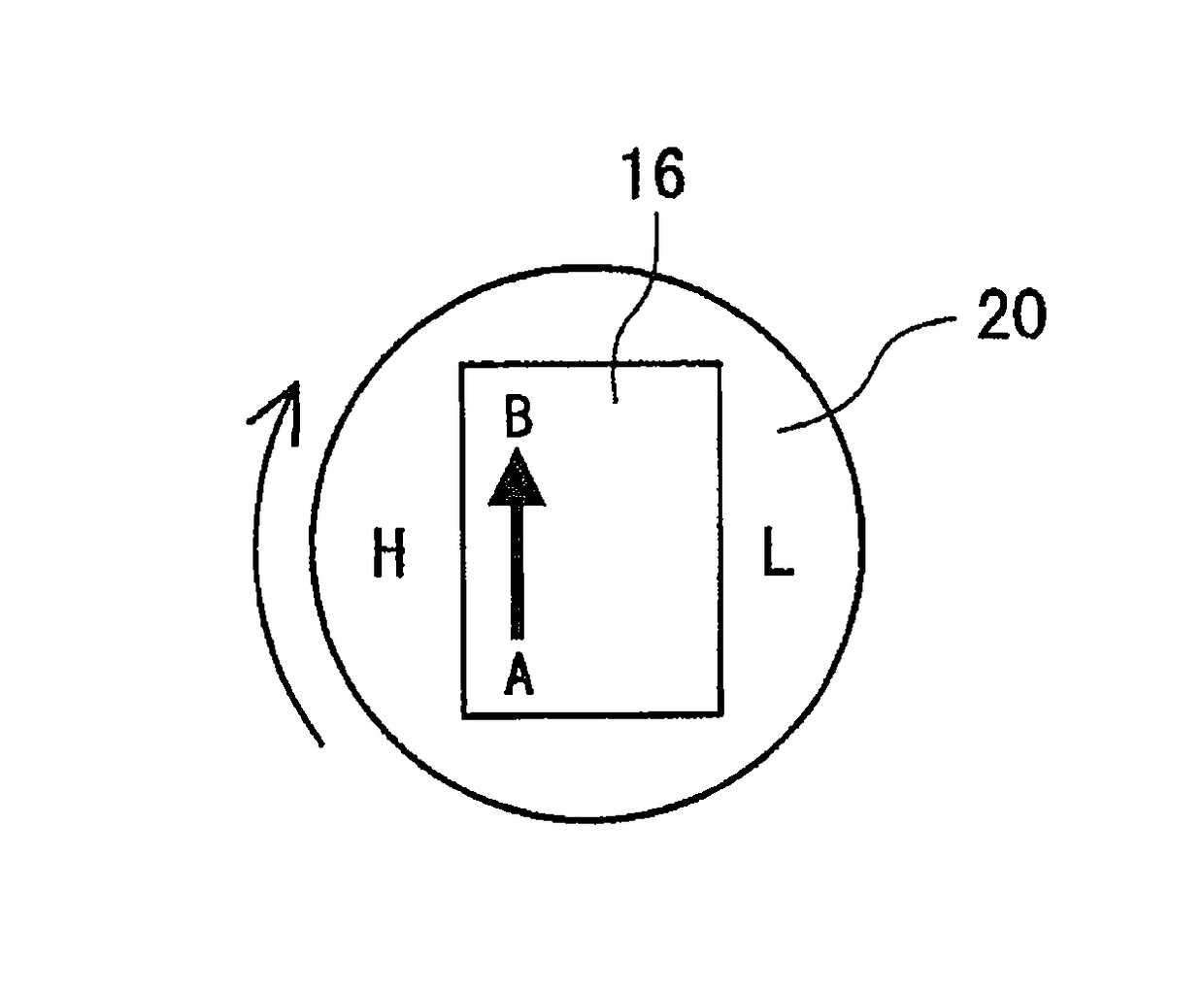
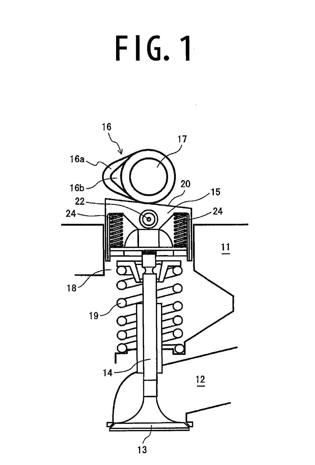
[0025]In FIG. 1, the reference numeral 11 designates a cylinder head of an automobile engine and the reference numeral 12 designates an intake port. The reference numerals 13, 14, 15 and 16 designate an intake valve, a valve stem, a valve lifter with a variable lift mechanism and a cam, respectively. The reference numeral 16a designates a high lift cam and the reference numeral 16b designates a low lift cam. The high lift cam 16a and the low lift cam 16b are integrated with a cam shaft 17 for unitization.

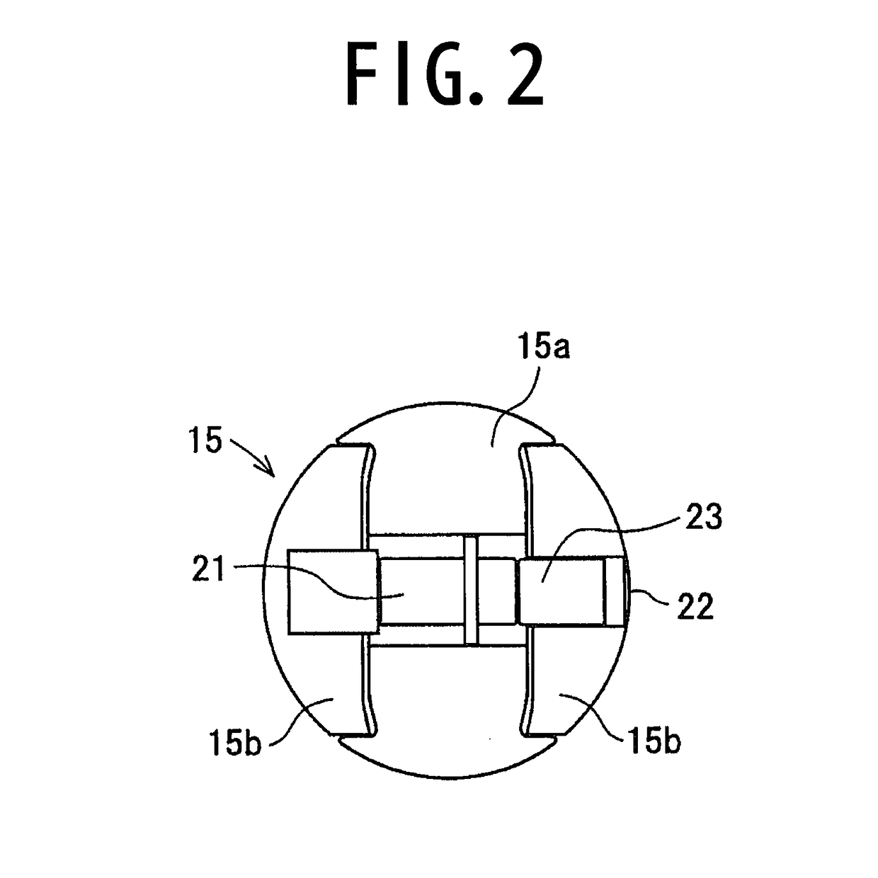
[0026]The reference numeral 18 designates a cylinder bore and the intake port 12 is closed by pressing the intake valve 13 against the intake port 12 using a coil spring 19 provided in the cylinder bore 18. The cam 16 (16a or 16b) is constituted so as to press the valve lifter 15 downward in FIG. 1 against the spring force of the coil spring 19, thereby opening the intake valve 13. The reference numeral 20 designates a cam sliding contact surface of the valve lifter 15. The cam 16 s...


PUM


Abstract

A valve lifter with a variable lift mechanism is required to be deployed at a predetermined angle with respect to a cam unit, and the present invention is intended to achieve this requirement with a simple configuration without too much processing such as a fitting of the conventional longitudinal groove and a pin.A cam sliding contact surface of a valve lifter on which a high lift cam and a low lift cam slides is formed to be a smooth inclined surface and a cam slide starting point is lower than a cam slide terminating point, thereby establishing an elevation difference between the cam slide starting point and the cam slide terminating point. As a result, since the high lift cam and the low lift cam always move uphill on the cam sliding contact surface, namely, from the low cam slide starting point toward the high cam terminating point along the slope of the cam sliding contact surface, the valve lifter is not subjected to a force around the reciprocating axis from the cam and therefore, the direction of the valve lifter is maintained constant.

Description

CROSS-REFERENCES TO RELATED APPLICATIONS[0001]This application claims priority to International Patent Application No. PCT / JP2012 / 072158 filed on Aug. 31, 2012, the entire contents of which are hereby incorporated by reference.FIELD OF THE INVENTION[0002]The present invention relates to a cylindrical direct-action valve lifter of an internal combustion engine incorporated in a valve train of the internal combustion engine. Among such valve lifters, the present invention particularly relates to a valve lifter with a variable lift mechanism.[0003]This type of the valve lifter is configured to enable an amount of lift to be altered between a high valve lift and a low valve lift by switching operation of a cam unit integrating a high lift cam and a low lift cam between its high lifter with a high lift cam sliding contact surface and its low lifter with a low lift cam sliding contact surface. Generally, in the case where the lift is high, a high efficiency can be achieved at a high revol...

Claims


Application Information

Patent Timeline
Patent Type & Authority Patents(United States)
IPC IPC(8): F01L1/14F01L1/02F01L13/00
CPCF01L1/02F01L1/143F01L13/0036F01L2107/00F01L2810/04F01L2307/00
Inventor YASUIKE, MAKOTO
Owner NITTAN VALVE CO LTD
Why Eureka
Try Eureka