
Power supply system and method for converting power thereof

a power supply system and power supply technology, applied in the field of circuit structure and method, can solve the problems of increasing the burden of the power grid, increasing the size and production cost of the power supply system, and difficulty in integrating green energy such as solar/wind power in future systems, so as to reduce the power impact reduce the size and production cost of the power supply system, and reduce the size of the input power grid

Active Publication Date: 2017-05-16
DELTA ELECTRONICS INC
View PDF16 Cites 0 Cited by
  • Summary
  • Abstract
  • Description
  • Claims
  • Application Information

AI Technical Summary

Benefits of technology

This solution decreases the power requirements of the input grid, reduces the size and production cost of the power supply system, and allows for continuous and stable power delivery to electric buses without overburdening the grid, while also facilitating the integration of green energy sources.

Problems solved by technology

Being promising in many aspects, the energy storage and charging of electric buses still remain a challenge.
However, this intermittent charging mode increases the burden of the power grid and may cause instability issues.
Furthermore, it is difficult for integrating green energy such as solar / wind power in future systems.
There has been much effort in trying to find solutions to the aforementioned problems.

Method used


Image

  • Power supply system and method for converting power thereof
  • Power supply system and method for converting power thereof
  • Power supply system and method for converting power thereof

Examples


Embodiment Construction

[0029]The detailed description provided below in connection with the appended drawings is intended as a description of the present examples and is not intended to represent the only forms in which the present example may be constructed or utilized. The description sets forth the functions of the example and the sequence of steps for constructing and operating the example. However, the same or equivalent functions and sequences may be accomplished by different examples.

[0030]Unless otherwise defined herein, scientific and technical terminologies employed in the present disclosure shall have the meanings that are commonly understood and used by one of ordinary skill in the art. Unless otherwise required by context, it will be understood that singular terms shall include plural forms of the same and plural terms shall include the singular. Specifically, as used herein and in the claims, the singular forms “a” and “an” include the plural reference unless the context clearly indicates ot...


PUM


Abstract

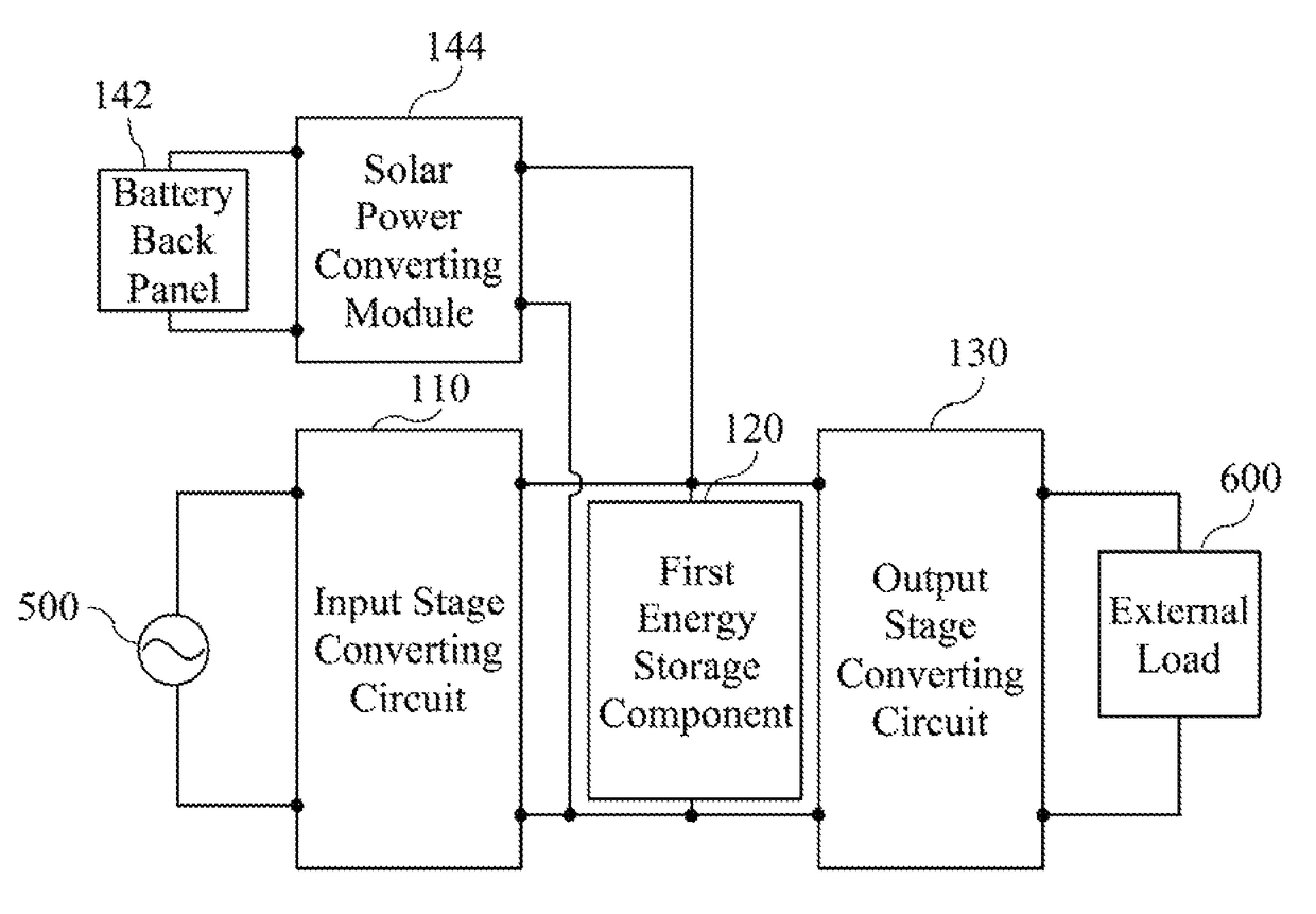
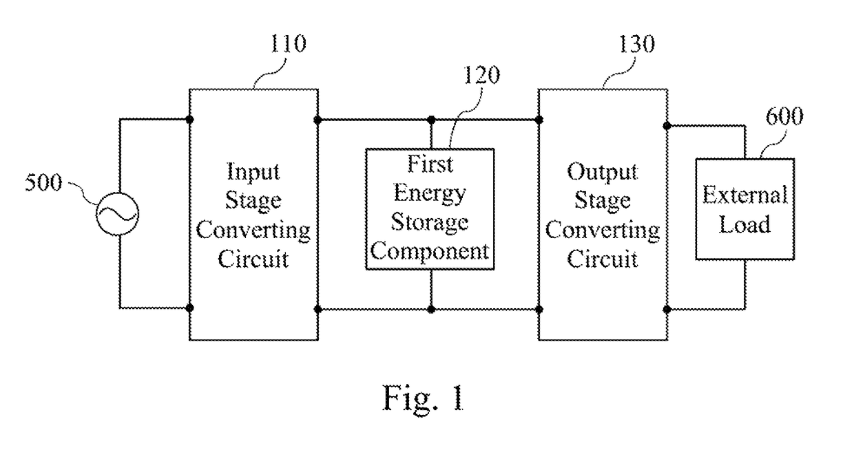
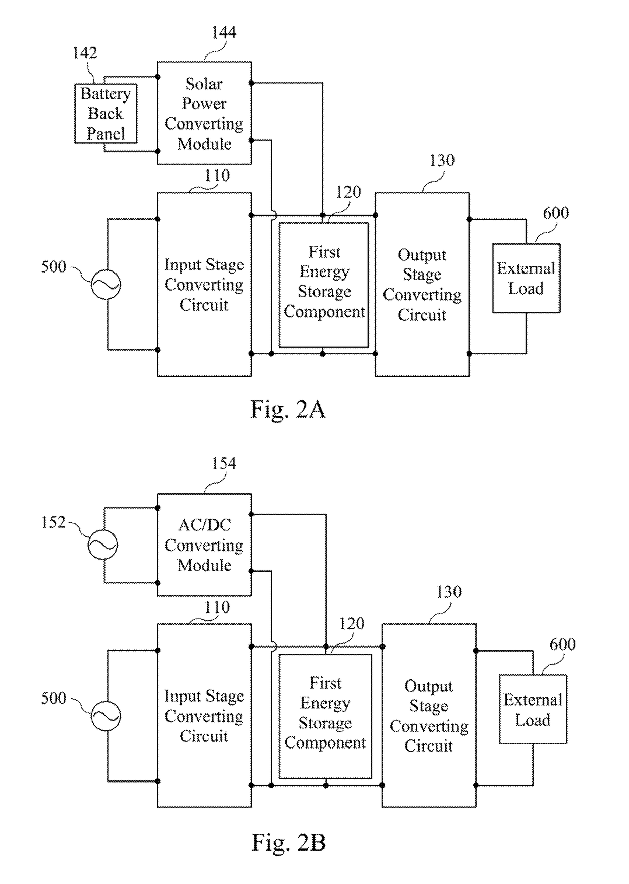
A power supply system includes an input stage converting circuit, a first energy storage component, and an output stage converting circuit. The first energy storage component is electrically coupled to the input stage converting circuit, and the output stage converting circuit is electrically coupled to the first energy storage component. The input stage converting circuit is configured to charge the first energy storage component, and the first energy storage component stores charging electricity. The output stage converting circuit is configured to convert the charging electricity into output electricity and provide the output electricity to a load. The input stage converting circuit has a first electric power, and the output stage converting circuit has a second electric power greater than the first electric power. A method for converting power of the power converter is also disclosed herein.

Description

RELATED APPLICATIONS[0001]This application claims priority to China Application Serial Number 201310218298.9, filed Jun. 4, 2013, which is herein incorporated by reference.BACKGROUND[0002]Field of Invention[0003]The embodiment of the present invention relates generally to a circuit structure and method; more particularly, to a power supply system and method for converting power thereof.[0004]Description of Related Art[0005]Electric vehicles are drawing more and more interests in recent years as they are more ecologically friendly compared with traditional gasoline powered vehicles. In particular, electric buses are booming in the development of urban public transportation.[0006]Being promising in many aspects, the energy storage and charging of electric buses still remain a challenge. One economical way is to charge the electric bus batteries when the bus stops at a station, with the intermittent charging mode featured by high charging power during a short period of time. However, t...

Claims


Application Information

Patent Timeline
Patent Type & Authority Patents(United States)
IPC IPC(8): H02J1/00B60L8/00B60L11/18
CPCH02J1/00B60L8/003B60L11/1812B60L11/1837B60L11/1844Y02T90/163Y04S10/126Y10T307/367Y02T90/128Y02T90/14B60L2230/22B60L2230/24B60L2230/30Y02E60/721Y02T10/7005Y02T10/7072Y02T10/7083Y02T90/121Y02T90/127B60L53/22B60L53/32B60L53/63B60L53/51B60L53/52B60L53/53Y02E60/00Y02T10/70Y02T90/12Y02T90/16
Inventor GUO, XING-KUANXIA, LI-TAO
Owner DELTA ELECTRONICS INC
Learn More