
Submersible power generators and method of operating thereof

a technology of liquid vapor generator and submerged power, which is applied in the direction of machines/engines, mechanical equipment, and borehole/well accessories, etc., can solve the problems of more standard renewable power sources, inability to operate undersea, and inability to meet the requirements of undersea operation,

Inactive Publication Date: 2017-05-16
GENERAL ELECTRIC CO
View PDF32 Cites 120 Cited by
  • Summary
  • Abstract
  • Description
  • Claims
  • Application Information

AI Technical Summary

Benefits of technology

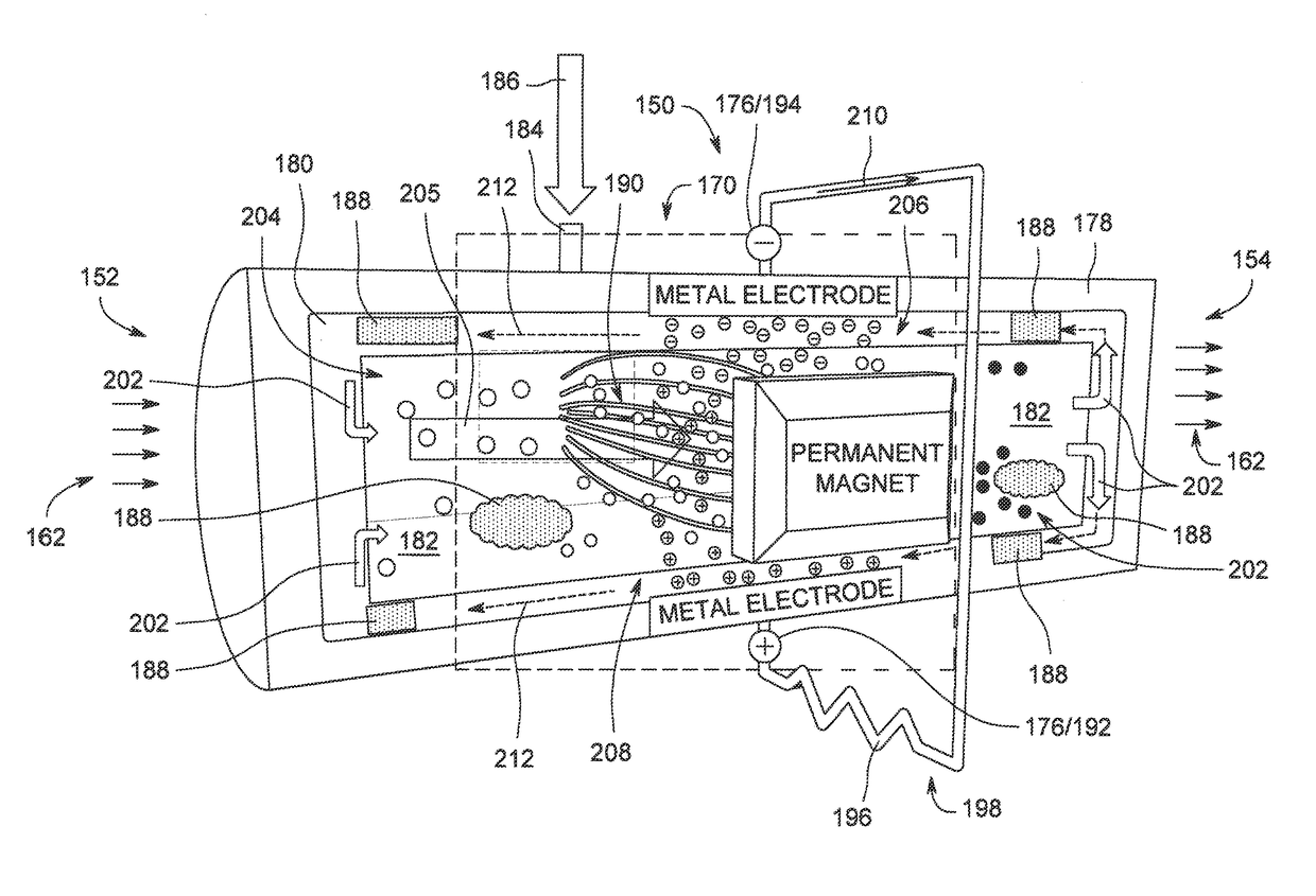
The patent describes a submersible liquid-vapor generator (LVG) that can generate power in an undersea environment. The LVG includes an evaporator portion, a magnetic field apparatus, and a condenser portion that work together to create a hybrid working vapor. The LVG also has a wick structure that defines a hybrid working liquid flow path. The method involves transferring heat energy from a heat source to the hybrid working liquid, inducing a voltage on an electric current carrying conductor, and then condensing the hybrid working vapor back into the liquid. This technology can provide a more efficient way to generate power in underwater environments.

Problems solved by technology

As such, most standard power generation devices that rely on fossil fuels are not practical for undersea operations.
Also, more standard renewable power sources, e.g., wind and solar are also not available.
Nuclear and chemical conversion power generation systems are also impractical for widespread use in undersea applications (other than submarines) due to practical considerations, e.g., environmental regulations.
However, since greater efficiencies are found with higher temperatures, such MHD systems are limited by the materials available, and such materials, excluding expensive exotic materials, are susceptible to temperature and corrosion effects.
However, such known MHD systems require intricate plumbing configurations for multiple flow circuits that include metal particle injection and mixing apparatus and metal particle separation apparatus.
As such, known MHD systems are not suitable for extended deployments in undersea environments.

Method used


Image

  • Submersible power generators and method of operating thereof
  • Submersible power generators and method of operating thereof
  • Submersible power generators and method of operating thereof

Examples


Embodiment Construction

[0017]In the following specification and the claims, reference will be made to a number of terms, which shall be defined to have the following meanings.

[0018]The singular forms “a”, “an”, and “the” include plural references unless the context clearly dictates otherwise.

[0019]“Optional” or “optionally” means that the subsequently described event or circumstance may or may not occur, and that the description includes instances where the event occurs and instances where it does not.

[0020]Approximating language, as used herein throughout the specification and claims, may be applied to modify any quantitative representation that could permissibly vary without resulting in a change in the basic function to which it is related. Accordingly, a value modified by a term or terms, such as “about”, “approximately”, and “substantially”, are not to be limited to the precise value specified. In at least some instances, the approximating language may correspond to the precision of an instrument for...


PUM


Abstract

A submersible liquid-vapor generator (LVG) includes an evaporator portion in heat transfer communication with a heat energy source. The LVG also includes a magnetic field apparatus coupled in flow communication with the evaporator portion. The LVG further includes a condenser portion coupled in flow communication with the magnetic field apparatus. The LVG also includes a hybrid working fluid including nanoparticles. The evaporator portion, the magnetic field portion, and the condenser portion at least partially define a hybrid working vapor flow path. The LVG further includes an electrically non-conductive wick structure coupled in flow communication with the evaporator portion and the condenser portion. The wick structure at least partially defines a hybrid working liquid flow path extending between the condenser portion and the evaporator portion.

Description

BACKGROUND[0001]The field of the disclosure relates generally to electric power generation equipment and, more particularly, to submersible liquid-vapor generators (LVGs).[0002]Continued exploration of undersea environments requires submerged, proximate, compact, and reliable electric power generation sources with sufficient capacity to provide a high power density for extended periods of time. As such, most standard power generation devices that rely on fossil fuels are not practical for undersea operations. Also, more standard renewable power sources, e.g., wind and solar are also not available. Other exotic power generation systems include thermoelectric (TE), photon enhanced thermionic (PET), and thermophotovoltaic (TPV). In general, TE-based systems require a large temperature drop to be effective, a condition not typically found in undersea environments. PET systems and TPV systems require exposure to the sun. Nuclear and chemical conversion power generation systems are also i...

Claims


Application Information

Patent Timeline
Patent Type & Authority Patents(United States)
IPC IPC(8): F03G7/05F01K25/12H02K44/08H02K44/12E21B41/00
CPCF03G7/05E21B41/0085F01K25/12H02K44/08H02K44/085H02K44/12Y02E10/34Y02E10/30
Inventor WEAVER, STANTON EARLBRAY, JAMES WILLIAMBOWMAN, MICHAEL JOHN
Owner GENERAL ELECTRIC CO
Learn More