Thermally controllable energy generation system

a technology of energy generation system and controllable device, which is applied in the direction of thermoelectric devices, electrochemical generators, temperature-sensitive devices, etc., can solve the problems of not being able to meet the current the cost of energy production is not currently born by the cost of energy production, and the conversion of petroleum to electrical energy is estimated to be only 9% efficient, so as to achieve the effect of easy manufacturing and without the need for expensive machining or manufacturing processes

Active Publication Date: 2017-04-25
CONCEPTUAL WERKS LLC
View PDF7 Cites 1 Cited by
  • Summary
  • Abstract
  • Description
  • Claims
  • Application Information

AI Technical Summary

Benefits of technology

[0008]Accordingly, several objects and advantages of the technology are: (a) to provide a method of electrical power generation which can be produced by a variety of materials that are readily available in most parts of the world; (b) to provide a method of electrical power generation that is easily manufactured with age-old, continuous or batch, printing and painting techniques and without the need for expensive machining or manufacturing processes; (c) to provide a method of electrical power generation that does not involve the emission of particulates, radioactive waste, greenhouse gases or other harmful pollutants; (d) to provide a method of electrical power generation that operates both at very low temperatures (below room temperature) and at very high temperatures (above 3000 K) as well as, those in between; (e) to provide a method of electrical power generation that does not necessarily require a constant feed of input power for conversion purposes; (f) to provide a method of electrical power generation that merely requires the presence of heat in order to take advantage of the existing built-in potential, from the electrostatic force available between certain materials at their interfaces when they are joined; (g) to provide a method of electrical power generation that can have very flat dimensions, so as to be incorporated unobtrusively into existing areas such as walls, car hoods, airplane fuselages, roads, etc.; (h) to provide a method of electrical power generation that can be used in transportation vehicles, including but not limited to airplanes, bikes, cars, ships and trucks; (i) to provide a method of electrical power generation where the power generation devices can be employed in familiar configurations already used by batteries, generators and capacitors to take advantage of already existing infrastructure.

Problems solved by technology

The manufacture of these devices, although well established, can still be expensive and complicated.
Most power generation today occurs from the irreversible combustion of fossil fuels and although this form of energy conversion is still less expensive than other types of electricity generation, the long term damage to the environment and human health is not currently born by the cost of energy production.
In addition, the conversion of petroleum to electrical energy is estimated to be only 9% efficient.
The cost of electricity produced from solar cells is still quite expensive when compared to fossil fuel based electrical power generation, and there remains the problem of energy storage in the absence of relevant light frequencies (night time).
Other types of energy conversion systems based on wind, hydroelectric, and nuclear energy input, while cost effective in some cases, still negatively impact the environment and / or may require large capital outlays.
Other more exotic types of electrical generation devices such as thermoelectric, thermionic and magneto-hydrodynamic ones do not currently have the conversion efficiencies necessary to make them adaptable to mass electrical power production and in addition, are complicated to manufacture.
Even with the current price of oil as of Oct. 2, 2006 hovering at $61 / barrel, alternative forms of energy conversion are still not cost effective to produce and operate.
Those forms of energy input (for example, coal and nuclear) that are considered cost competitive with petroleum-based energy inputs create damage to the environment through the emission of greenhouse gases and particulates or through the production of radioactive waste.

Method used


Image

  • Thermally controllable energy generation system
  • Thermally controllable energy generation system
  • Thermally controllable energy generation system

Examples


Embodiment Construction

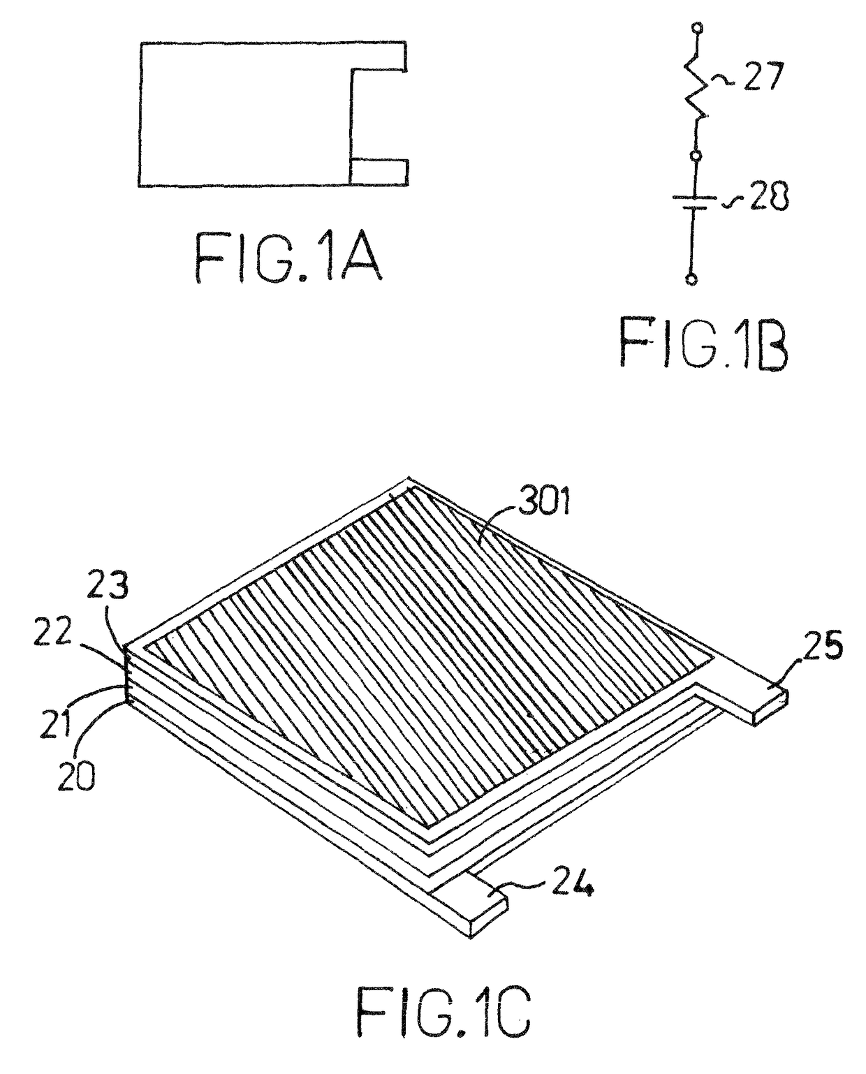
[0023]The present technology, a new type of electrical power generation device, is based on the purposeful layering of different materials, oxides, semiconductors, metals and carbons, such that voltage differentials are manifested at the interface of the materials and an overall voltage value is exhibited between the anode and cathode of the device. The production of electricity from this device is caused by the creation of a built-in potential across the interface between stable materials with dissimilar electron configurations and densities. Once the correct series of layers are applied, the device may then be treated as any electrical power device and stacked in series or parallel, in order to reach a desired voltage or current output.

[0024]Electrons oscillate and emit electromagnetic energy in the form of waves. These waves possess a frequency distribution based on Planck's formula. Also, due to the connections between atoms, the displacement of one or more atoms from their equi...


PUM

PropertyMeasurementUnit
temperaturesaaaaaaaaaa
temperatureaaaaaaaaaa
thicknessesaaaaaaaaaa

Abstract

A thermally controllable energy generation system comprising an insulated, thermally-enhanced generator with a power circuit for conveying power. The thermally enhanced generator and its available voltage is controlled by a circuit which changes the ambient temperature of the generator through the use of a heating element and heating circuit. A controller circuit is in communication with the temperature sensor, the control circuit, the heating circuit and the power circuit. The thermally enhanced generator includes at least one cell, which comprises a layer of electron-rich donor material in contact with a layer of hole-rich acceptor material, sandwiched between an anode and a cathode. One of the layers is a stabilized mixture of carbon and an ionic material (carbon matrix) and the other layer is a stabilized oxide mixed with an ionic material (oxide matrix).

Description

CROSS REFERENCE TO RELATED APPLICATIONS[0001]This application is a divisional of U.S. Non-Provisional application Ser. No. 11 / 543,001, filed Oct. 4, 2006, which claims the benefit of priority to U.S. Provisional Application No. 60 / 723,696, filed on Oct. 5, 2005, the disclosures of both of which are incorporated herein by reference.FIELD OF THE TECHNOLOGY[0002]This technology relates to the generation of electric energy by a solid-state device and more particularly, by the use as a voltage source of thermally enhanced, built-in potentials arising at the junction between dissimilar materials including metals, semiconductors, ceramics (oxides, carbides, etc.) and carbons (graphite, charcoal).BACKGROUND OF THE TECHNOLOGY[0003]Electrical power generation devices use power inputs including, but not limited to electromagnetic waves (sunlight, infrared light, etc.), thermal energy, mechanical energy and nuclear energy and then convert these different forms of energy inputs into useable elec...

Claims


Application Information

Patent Timeline
Patent Type & Authority Patents(United States)
IPC IPC(8): H01L31/042H01L35/02H01L35/30H01M14/00H01L35/28H01G9/15H01L37/00H01G9/21
CPCH01L35/02H01G9/15H01L35/28H01M14/00H01M14/005H01G9/21H01L37/00H10N10/80H10N10/10H10N15/00
Inventor BERETICH, THOMAS
Owner CONCEPTUAL WERKS LLC
Why Eureka
Try Eureka