
Stacked solid-state image sensor and imaging apparatus including the same

a solid-state image sensor and imaging apparatus technology, applied in the field of small form factor solid-state image sensors, can solve the problems of reducing image resolution or optical sensitivity, consuming a larger amount of electric power for further ccd sensors, and reducing the image sensing area, so as to eliminate missing pixel information and view the same area.

Active Publication Date: 2017-04-25
SHIZUKUISHI MAKOTO
View PDF47 Cites 12 Cited by
  • Summary
  • Abstract
  • Description
  • Claims
  • Application Information

AI Technical Summary

Benefits of technology

[0018]Example embodiments provide a MOS sensor that is capable of preventing the dead space on the sensor surface. Example embodiments further provide, advantageously small form factor imaging apparatus that are provided with such a MOS sensor having optical symmetry. In addition, example embodiments further provide a MOS sensor that is capable of preventing electro-static discharge breakdown of the MOS structure, and a manufacturing method thereof.

Problems solved by technology

Further CCD sensors may consume a larger amount of electric power compared to MOS sensors.
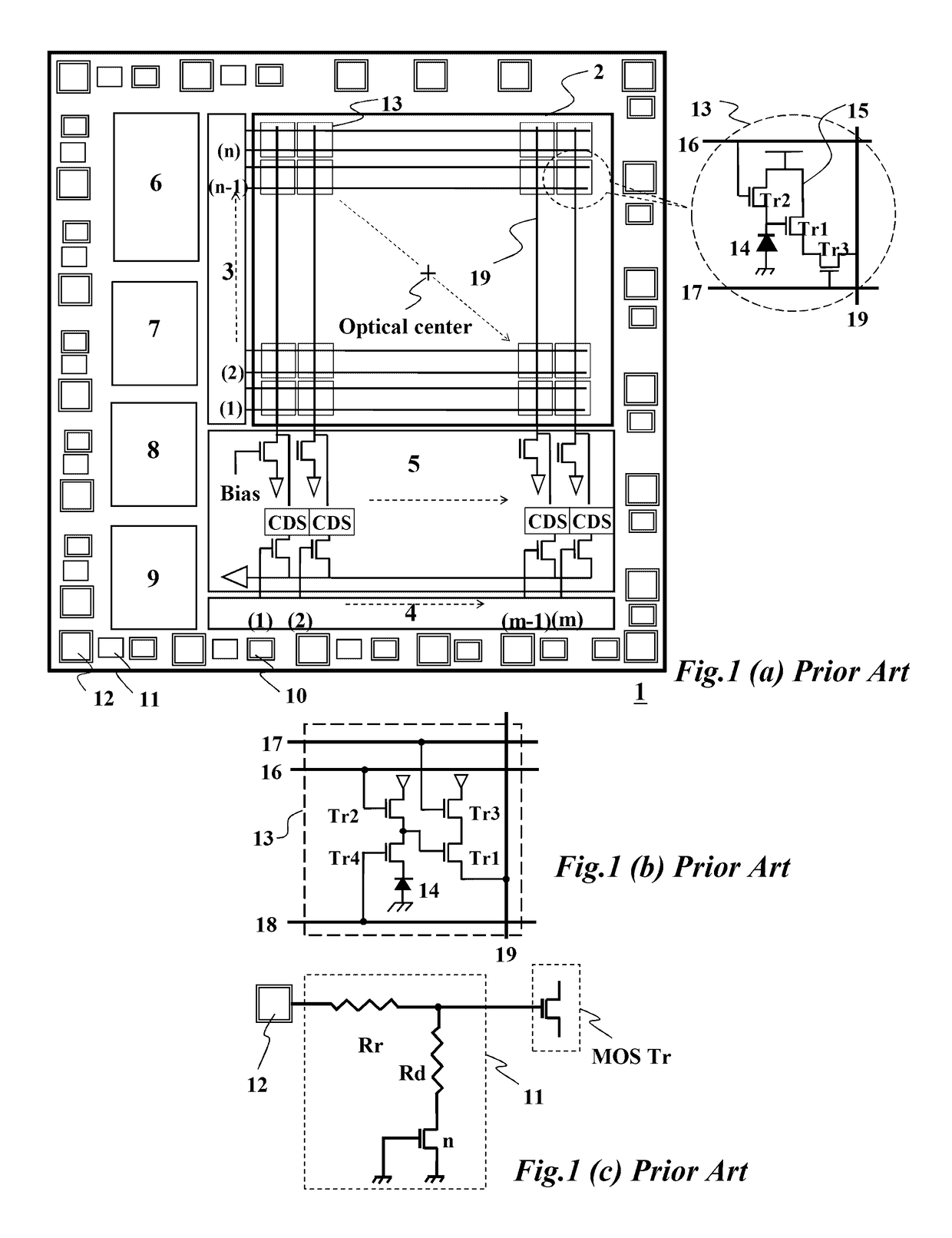
However, it may be difficult for the conventional solid-state image sensor to realize a small form factor because of the photo-insensitive portion (dead space) which surrounds an image sensing area on the image sensor.
However, in either case, image qualities such as image resolution or optical sensitivity may be degraded.
As for the stacked sensor structure, input protection circuits may be required for each input terminal between the chips in addition to externally exposed input terminals, otherwise MOS transistor input gate insulating material may be damaged from an electro-static discharge (ESD).
Consequently, an imaging system using such a MOS sensor according to example embodiments may become smaller and more compact.
Consequently, an imaging system using such a MOS sensor may become even smaller and more compact.

Method used


Image

  • Stacked solid-state image sensor and imaging apparatus including the same
  • Stacked solid-state image sensor and imaging apparatus including the same
  • Stacked solid-state image sensor and imaging apparatus including the same

Examples


Embodiment Construction

[0081]Detailed example embodiments are disclosed herein. However, specific structural and functional details disclosed herein are merely representative for purposes of describing example embodiments. Example embodiments may, however, be embodied in many alternate forms and should not be construed as limited to only the embodiments set forth herein.

[0082]Accordingly, while example embodiments are capable of various modifications and alternative forms, embodiments thereof are shown by way of example in the drawings and will herein be described in detail. It should be understood, however, that there is no intent to limit example embodiments to the particular forms disclosed, but to the contrary, example embodiments are to cover all modifications, equivalents, and alternatives falling within the scope of example embodiments. Like numbers refer to like elements throughout the description of the figures.

[0083]It will be understood that, although the terms first, second, etc. may be used h...


PUM


Abstract

An image sensor includes a first semiconductor chip having a first surface and a second surface, the first semiconductor chip a including an array of unit pixels configured to capture light corresponding to an image and to generate image signals based on the captured light; and a second semiconductor chip having a first surface and a second surface, the second semiconductor chip including first peripheral circuits configured to control the array of pixels and receive the generated image signals, the first peripheral circuits including a vertical scanning circuit, a horizontal scanning circuit, and a signal read-out circuit, the first semiconductor chip being stacked on the second semiconductor chip, the first semiconductor chip not being smaller than the second semiconductor chip.

Description

CROSS-REFERENCE TO RELATED APPLICATION[0001]This application claims priority under 35 U.S.C. §119 to Japanese Patent Application No. 2013-033593 filed on Feb. 22, 2013, in the Japanese Patent Office (JPO), the entire contents of which are incorporated herein by reference.BACKGROUND[0002]1. Technical Field[0003]Example embodiments relate to a small form factor solid state image sensor, a method of manufacturing the same, and an imaging apparatus.[0004]2. Related Art[0005]Types of solid-state image sensors that are used for various electronic imaging apparatus like video and still cameras include, for example, a charge-coupled device (CCD) type sensor and a metal-oxide semiconductor (MOS) type sensor. Previously, CCD sensors generally had better sensitivity and image quality than the MOS sensors. However, CCD sensors may require a customized CCD manufacturing process and an additional support device like a driver IC on a circuit board. Further CCD sensors may consume a larger amount o...

Claims


Application Information

Patent Timeline
Patent Type & Authority Patents(United States)
IPC IPC(8): H01L27/00H01L27/146H04N5/335
CPCH01L27/14634H01L27/1469H04N5/335H01L27/14605H04N25/00
Inventor SHIZUKUISHI, MAKOTO
Owner SHIZUKUISHI MAKOTO
Learn More