
Circuits and methods for reducing interference that spectrally overlaps a desired signal based on dynamic gain control and/or equalization

a technology of dynamic gain control and equalization, applied in the direction of orthogonal multiplex, multiplex communication, amplifier modification to reduce non-linear distortion, etc., can solve the problems of reducing the effectiveness of adversaries, distorted received signal collection, and sensitive satellite signals received by user terminals. , to achieve the effect of reducing interference, reducing interference, and reducing interferen

Active Publication Date: 2017-04-18
THE AEROSPACE CORPORATION
View PDF41 Cites 8 Cited by
  • Summary
  • Abstract
  • Description
  • Claims
  • Application Information

AI Technical Summary

Benefits of technology

The patent describes a system and method for reducing interference in a digitized signal. The system includes a binning subcircuit to separate the input signal into different spectral bins, with one bin containing interference. A power analysis subcircuit checks the power level of the bins and generates a control signal to maintain system linearity. This control signal can be used to adjust the gain of an amplifier. Additionally, the system includes a residual interference removal subcircuit that removes a portion of the interference from the signal using equalization circuitry. The method also includes steps for downconverting, digitizing, and removing interference from an RF signal. Overall, the system and method can improve the quality of signals and reduce interference.

Problems solved by technology

For example, satellite signals received by user terminals are susceptible to interference contained in satellite downlinks as well as interference received from terrestrial sources.
As a result, the object of frequency hopping is to force the adversary to dilute its resources over the wider bandwidth which reduces the adversary's effectiveness.
However, if a signal input to the receiver has a power that falls within the nonlinear range of the receiver, then the received signal collection is distorted and communication performance is degraded.
If the receiver receives interference that falls within the same portion of the electromagnetic spectrum as the desired group of signals, then the receiver may not distinguish the interference from the group of signals again degrading communication performance.
However, if the power of the interference is sufficiently high that nonlinear receiver operation occurs, not only may the interference obscure desired spectral components but also cause additional signal distortion.
This additional receiver distortion may include suppression of desired signals and generation of intermodulation products between design signal components and the interference, resulting in additional degradation in receiver performance.
However, increasing the linear range of the receiver may be expensive, and also may require a larger power supply to operate the modified circuitry.
However, its iterative nature makes this approach is relatively slow, and thus less able to respond to rapidly changing interference.
Such A / D converters become nonlinear for power inputs that are much lower than would cause nonlinearities in otherwise similar analog circuitry.
Such AGC circuitry uses time averaging techniques to reduce the analog levels at the A / D input, and like conventional adaptive notch filters, the time averaging limits the ability to respond to dynamically varying interference signals.
Transmitters also can be negatively impacted by interference that spectrally overlaps a desired signal.
Interfering signals in addition to the desired signals can result in nonlinear transmitter operation which distorts and degrades the desired transmitted signals.
The effectiveness of these techniques is significantly degraded by receiver nonlinearities.

Method used


Image

  • Circuits and methods for reducing interference that spectrally overlaps a desired signal based on dynamic gain control and/or equalization
  • Circuits and methods for reducing interference that spectrally overlaps a desired signal based on dynamic gain control and/or equalization
  • Circuits and methods for reducing interference that spectrally overlaps a desired signal based on dynamic gain control and/or equalization

Examples


examples

[0085]The following examples are intended to be purely illustrative, and not limiting.

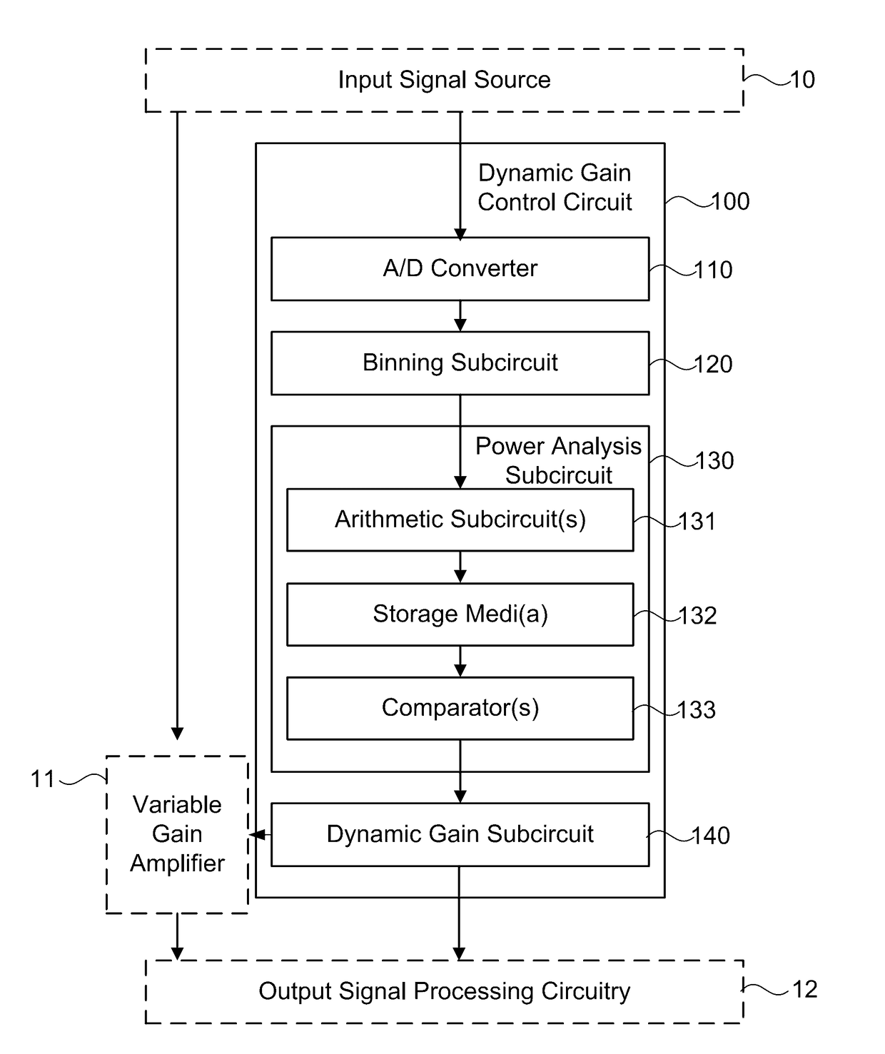
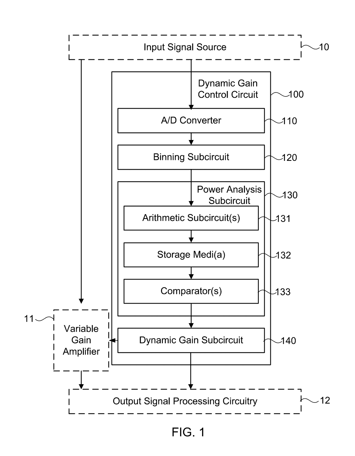
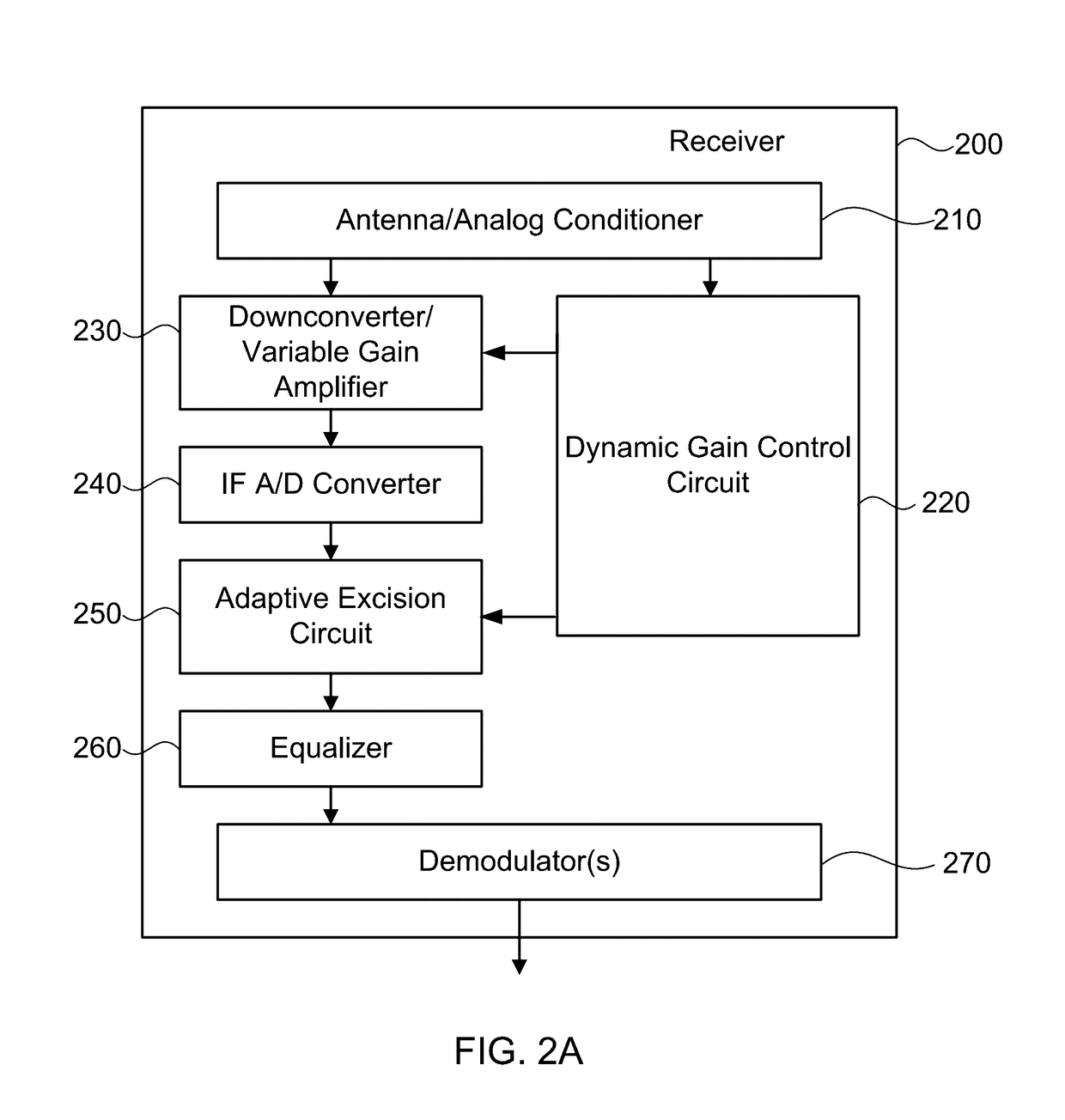
[0086]Potential performance characteristics of the present circuits and methods were characterized by using MATLAB (MathWorks, Natick, Mass.) to simulate receiver systems such as illustrated in FIG. 5 and as described herein with reference to FIGS. 1 and 2A-2B. MATLAB was used to simulate a transmitter such as illustrated in FIG. 5 that included a random integer generator block, integer to bit converter block, convolutional encoder block, bit to integer converter block, quadrature phase shift keying (QPSK) modulator at baseband block, and raised cosine transmit filter block to generate a convolution coded signal. Additive white Gaussian noise (AWGN) and an interference signal were added to the convolution coded input signal and provided as input to a receiver that included blocks for DGC, excision, and equalization, which blocks could be used in any desired combination with one another. The DGC blo...


PUM


Abstract

A system is provided with circuits and methods for dynamically reducing interference to maintain linear system operation and mitigate interference degradation to desired signal components. The system can include a binning subcircuit system configured to divide the digitized input signal into a plurality of spectral bins each having a power level. A power analysis subcircuit can be coupled to the binning subcircuit and configured to compare a collective power level of spectral bins to a threshold level that would produce nonlinear system operation. Based upon the collective power level exceeding the threshold level, outputting a gain control signal to a variable gain amplifier so that the system remains linear. This dynamic gain control can be applied to systems that receive and / or transmit signals. Residual interference components that degrade signal components can be dynamically removed by excision and the distortion introduced by the excision process can be reduced with equalization circuitry.

Description

FIELD OF THE INVENTION[0001]This application generally relates to circuits and methods for reducing interference that spectrally overlaps a desired signal.BACKGROUND OF THE INVENTION[0002]Many techniques have been devised to reduce interference signals that otherwise may degrade communication systems, such as receivers or transmitters. For example, satellite signals received by user terminals are susceptible to interference contained in satellite downlinks as well as interference received from terrestrial sources.[0003]A receiver may be configured to receive and process signals that have broad bandwidth spectra and powers within a certain, expected, range. For example, a receiver on a satellite may be configured to receive a group of signals that share a common region of the electromagnetic spectrum, and are multiplexed with one another using techniques known in the art. In the multiplexing technique known as code division multiple access (CDMA), each signal of the group is encoded ...

Claims


Application Information

Patent Timeline
Patent Type & Authority Patents(United States)
IPC IPC(8): H04L27/08H04B1/10H04B1/04H04L27/26
CPCH04B1/10H04B1/0475H04L27/265H04B2001/0416H03F1/32H03F3/24H04J11/0066
Inventor CLARK, CHRISTOPHER J.DYBDAL, ROBERT B.WANG, FEI
Owner THE AEROSPACE CORPORATION
Learn More