
Active vibration/noise control apparatus

a noise control and active technology, applied in the direction of active noise control, sound producing devices, musical instruments, etc., can solve the problems of reducing the suppression effect, and achieve the effect of stable vibration/noise suppression and positive detection of vibration or nois

Inactive Publication Date: 2017-04-18
MITSUBISHI ELECTRIC CORP
View PDF13 Cites 2 Cited by
  • Summary
  • Abstract
  • Description
  • Claims
  • Application Information

AI Technical Summary

Benefits of technology

The present invention is an apparatus that can control vibration and noise in a way that adjusts a filter's step to match the signal-to-interference ratio. This helps to accurately detect and suppress vibration and noise, even if they fluctuate. In simple terms, this invention helps to prevent errors and achieve stable operation.

Problems solved by technology

Here, if interference unrelated to the controlled subject is provided to the detector, the apparatus responds to it, and offers a problem of deviating the amplitude and phase of the control signal, thereby reducing suppression effect, or a problem of the apparatus itself of producing extraordinary vibration or a strange sound.

Method used


Image

  • Active vibration/noise control apparatus
  • Active vibration/noise control apparatus
  • Active vibration/noise control apparatus

Examples


embodiment 1

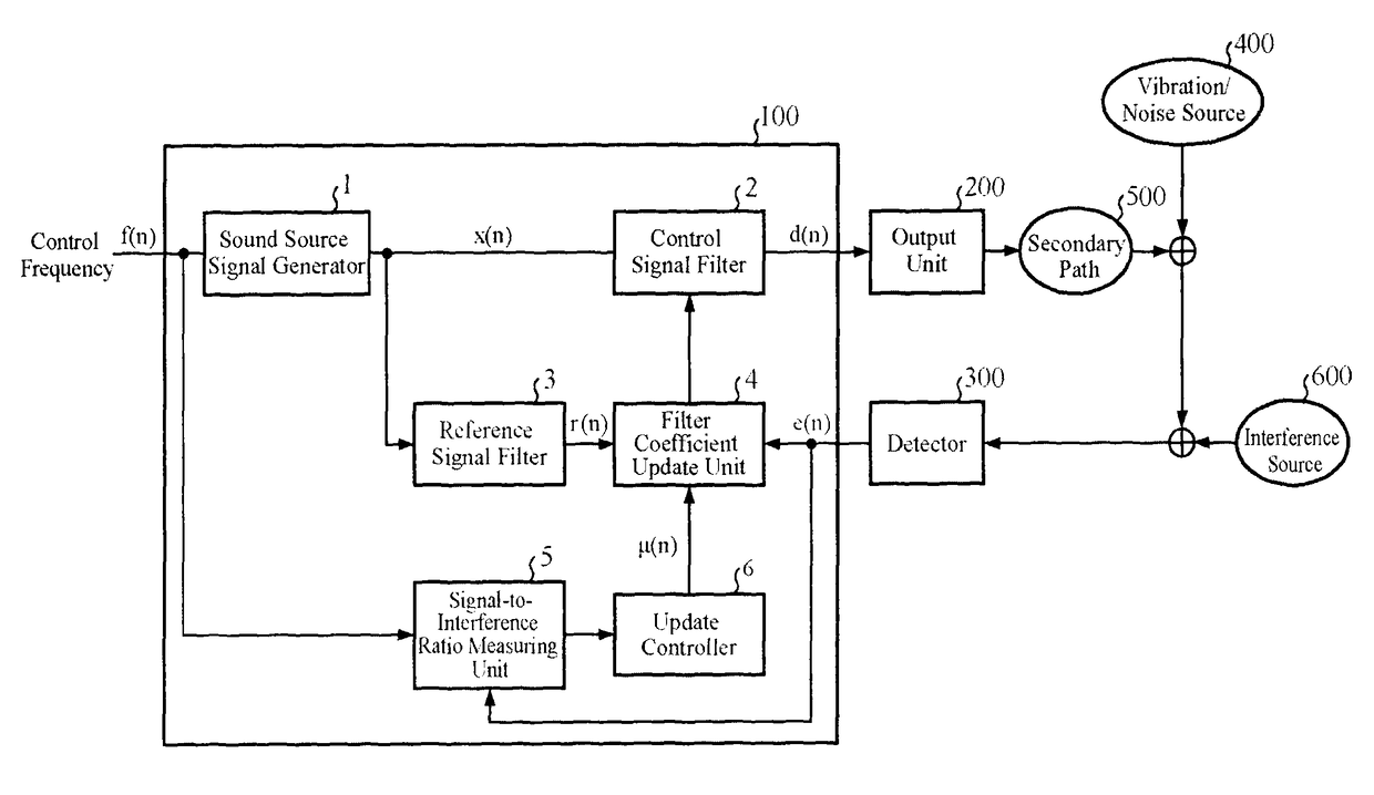
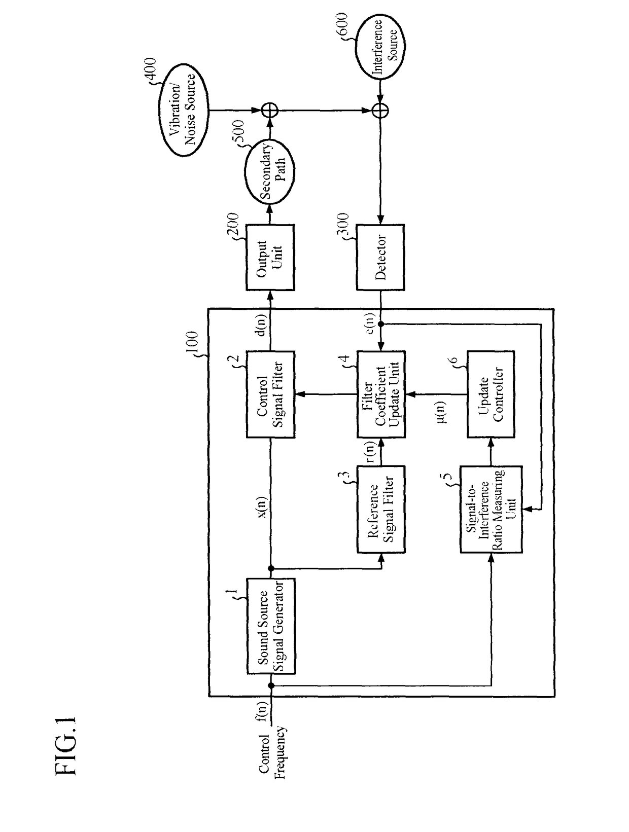
[0022]FIG. 1 is a block diagram showing a configuration of an active vibration / noise control apparatus of an embodiment 1 in accordance with the present invention.

[0023]As shown in FIG. 1, the active vibration / noise control apparatus 100 of the embodiment 1 in accordance with the present invention is connected to an output device 200 and a detector 300, which are placed outside the apparatus.

[0024]The active vibration / noise control apparatus 100 receives control frequency based on the frequency of the vibration / noise of a vibration / noise source 400 which is a controlled subject, and outputs a control signal produced in response to the input control frequency. Here, if the vibration / noise source is the engine of a car, for example, the control frequency is obtained by a method that measures the rotational frequency of the engine from an ignition pulse period, followed by making constant times the rotational frequency in accordance with the engine rotational order of the target vibrat...

embodiment 2

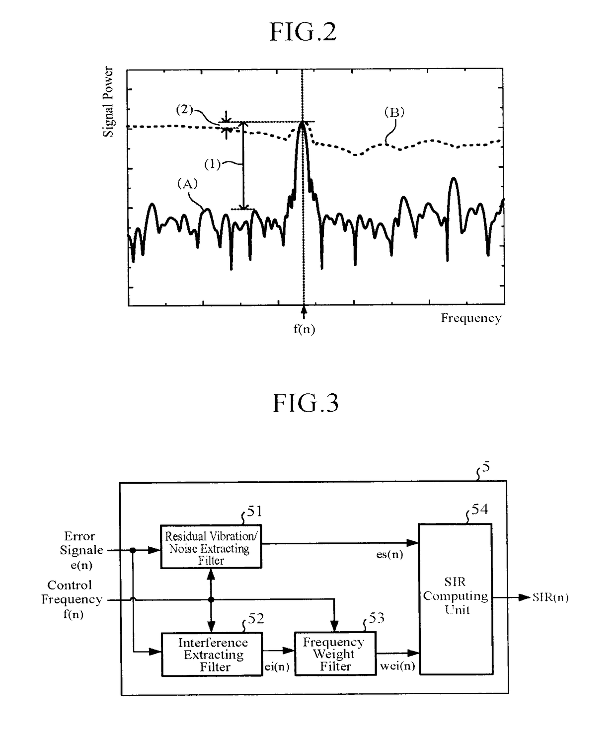
[0062]In the embodiment 1 in accordance with the present invention, as a method for calculating the signal-to-interference ratio SIR(n), the method is described for measuring the signal power of the residual vibration / noise signal es(n) and that of the interference signal ei(n) in the error signal e(n) using the band-pass filter or band-stop filter or the power spectrum analysis by the FFT, and for calculating the signal-to-interference ratio SIR(n).

[0063]However, depending on the vibration / noise source, there are some that change the frequency of the vibration / noise frequently owing to the variation of a rotation rate like a car engine, for example. In such a case, the method using the band-pass filter or band-stop filter must alter the frequency characteristics of the filter in accordance with the frequency of the vibration / noise, which requires frequent redesign of the filter and increases the computation amount of the processor. In addition, when the filter is composed of an IIR...


PUM


Abstract

A control signal filter 2 receives a sound source signal determined by a control frequency specified in conformity with the vibration / noise source that produces vibration / noise, and outputs a control signal. A filter coefficient update unit 4 updates coefficients of the control signal filter 2 in response to a sound source signal and an error signal. A signal-to-interference ratio measuring unit 5 outputs a signal-to-interference ratio determined from the vibration / noise and the interference contained in the error signal in response to the control frequency and error signal. An update controller 6 adjusts an update step of the filter coefficient update unit 4 in accordance with the signal-to-interference ratio.

Description

TECHNICAL FIELD[0001]The present invention relates to an active vibration / noise control apparatus for reducing vibration or noise produced by machinery, for example, by generating cancellation vibration or noise.BACKGROUND ART[0002]As a means for reducing vibration or noise which machinery produces, an active vibration control apparatus and an active noise control apparatus are known. Since the present invention is applicable to both of them, the instant specification refers to them as an active vibration / noise control apparatus collectively which means an “apparatus for controlling vibration or noise”. Likewise, as for “vibration or noise” of machinery, they are referred to as vibration / noise collectively.[0003]A conventional active vibration / noise control apparatus detects vibration or noise, which is a controlled subject, with a detector such as a vibration sensor or microphone, and controls it by outputting the same amplitude and anti-phase control signal for cancellation. As an...

Claims


Application Information

Patent Timeline
Patent Type & Authority Patents(United States)
IPC IPC(8): G10K11/178
CPCG10K11/178G10K2210/129G10K11/17881G10K11/17854G10K11/1781G10K11/17825G10K11/17817G10K11/17883G10K11/17835
Inventor YANO, ATSUYOSHI
Owner MITSUBISHI ELECTRIC CORP
Learn More