Method and apparatus for manufacturing optical display device

a technology of optical display and manufacturing method, which is applied in the direction of controlling lamination, instruments, other domestic objects, etc., can solve the problems cycle time, and high manufacturing speed of optical film sheets, and achieve the effect of high laminating accuracy

Inactive Publication Date: 2017-04-18
NITTO DENKO CORP
View PDF8 Cites 0 Cited by
  • Summary
  • Abstract
  • Description
  • Claims
  • Application Information

AI Technical Summary

Benefits of technology

[0014]An aim of the present invention is to provide a method and an apparatus for manufacturing an optical display device with high laminating accuracy, as mentioned above.

Problems solved by technology

Roll length of such an optical film laminate is about 900 m. However, manufacturing speed i.e., cycle time for such middle- or small-sized liquid-crystal display device is required to be two times higher than that for a large liquid-crystal display device, and laminating accuracy for an optical film sheet, such as a polarizing film supported on a carrier film, to be laminated to a liquid-crystal panel LC is also very severe.

Method used


Image

  • Method and apparatus for manufacturing optical display device
  • Method and apparatus for manufacturing optical display device
  • Method and apparatus for manufacturing optical display device

Examples


Embodiment Construction

(Overview of a Method and an Apparatus for Manufacturing an Optical Display Device)

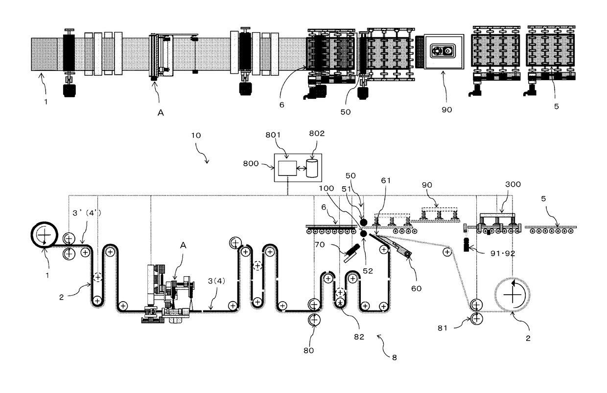
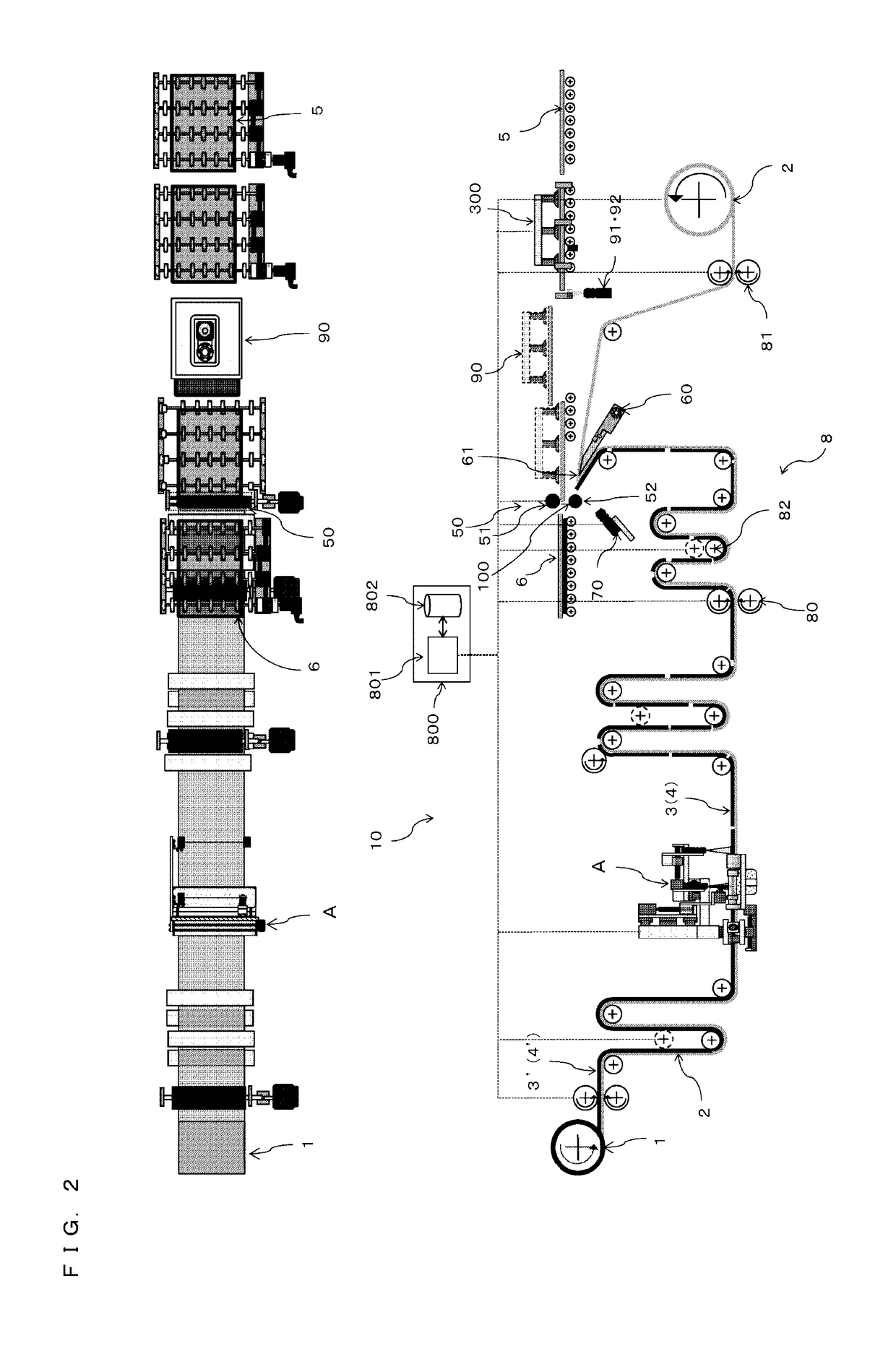
[0057]FIG. 2 illustrates a top view and a side view showing an entire apparatus 10 for manufacturing an optical display device 6 by laminating an optical film sheet 3 and a panel component 5 at a predetermined laminating position 100. As shown in FIG. 1, the optical film sheet 3 including an adhesive layer 4 is formed by forming a plurality of slit lines on an optical film 3′ laminated together with an adhesive layer 4′ on one of opposite surfaces of a long web of a carrier film 2 which configures an optical film laminate 1 with a width corresponding to a long side or a short side of the rectangular panel component 5.

[0058]The apparatus 10 used in an embodiment of the present invention may be, for example but not limited to, an apparatus configuring a part of a manufacturing system of liquid-crystal display devices for slate-PCs. The manufacturing system has, but not limited to, a linear channel and d...


PUM

PropertyMeasurementUnit
sizeaaaaaaaaaa
sizeaaaaaaaaaa
weightaaaaaaaaaa

Abstract

A method and an apparatus for manufacturing an optical display device by sequentially peeling a plurality of optical film sheets continuously supported on a long web of a carrier film and laminating the plurality of optical film sheets to a plurality of panel components are provided.

Description

CROSS REFERENCE TO RELATED APPLICATION[0001]This application claims the priority of Japanese Patent Application No. 2012-252808, filed on Nov. 19, 2012 in the JPO (Japanese Patent Office) and Japanese Patent Application No. 2013-198003, filed on Sep. 25, 2013 in the JPO. Further, this application is the National Phase application of International Application No. PCT / JP2013 / 076472 filed Sep. 30, 2013, which designates the United States and was published in Japanese.TECHNICAL FIELD[0002]The present invention relates to a method and an apparatus for manufacturing an optical display device. In particular, the present invention relates to a method and an apparatus for manufacturing an optical display device, the method and apparatus using a peeling member having a tip-end, for sequentially peeling a plurality of optical film sheets continuously supported via an adhesive layer on one of opposite surfaces of a carrier film together with the adhesive layer from the carrier film under peelin...

Claims


Application Information

Patent Timeline
Patent Type & Authority Patents(United States)
IPC IPC(8): B32B37/12B29C63/00B32B37/00B32B37/14B32B41/00B29C65/48B29C65/00B32B39/00G02F1/13B29L31/34
CPCB32B37/12B29C63/0095B32B37/025B32B37/14B32B37/187B32B41/00G02F2202/28B29C65/48B29C66/1122B29C66/472B29C66/83413B29L2031/3475B32B39/00B32B2457/20B32B2551/00G02F1/1303
Inventor YURA, TOMOKAZUKOYANAGI, TOKUHIDESHIBATA, SHOJINAKAZONO, TAKUYA
Owner NITTO DENKO CORP
Why Eureka
Try Eureka