
Composite magnetic core and magnetic element

a magnetic core and composite technology, applied in the direction of magnetic cores/yokes, inductances with magnetic cores, transformer/inductance magnetic cores, etc., can solve the problems of poor moldability and low mechanical strength delay in practical applications of compressed magnetic materials, and high production cost of amorphous foil bands. , to achieve the effect of simple compression molding, enhanced filling density of composite magnetic cores, and simplified configuration of compressed magnetic bodies

Inactive Publication Date: 2017-04-11
NTN CORP
View PDF23 Cites 6 Cited by
  • Summary
  • Abstract
  • Description
  • Claims
  • Application Information

AI Technical Summary

Benefits of technology

The present invention is about a composite magnetic core that is made by combining an injection-molded magnetic body and a compressed magnetic body. The compressed magnetic body is made of magnetic powders that are easily compression-molded and can enhance the filling density of the composite magnetic core. By combining the two magnetic bodies, the composite magnetic core has a desired configuration, excellent magnetic characteristics, and is compact and inexpensive. Additionally, the cost of equipment for producing the composite magnetic core is lower, the productivity of the equipment is higher, the production cost is lower, and the degree of freedom in designing the configuration is higher.

Problems solved by technology

But the compressed magnetic materials have a poor moldability and a low mechanical strength after they are fired.
The production cost of the amorphous foil band is high because it is produced through a winding process, a cutting process, and a gap forming process.
For this reason, practical applications of these magnetic materials have been delayed.

Method used


Image

  • Composite magnetic core and magnetic element
  • Composite magnetic core and magnetic element
  • Composite magnetic core and magnetic element

Examples


Embodiment Construction

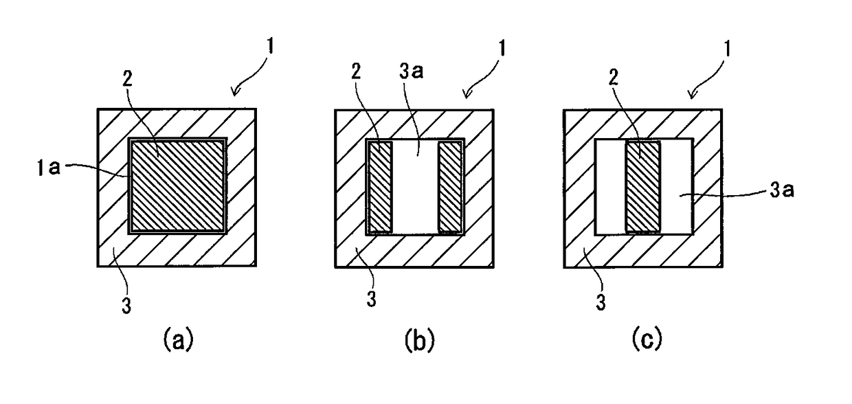
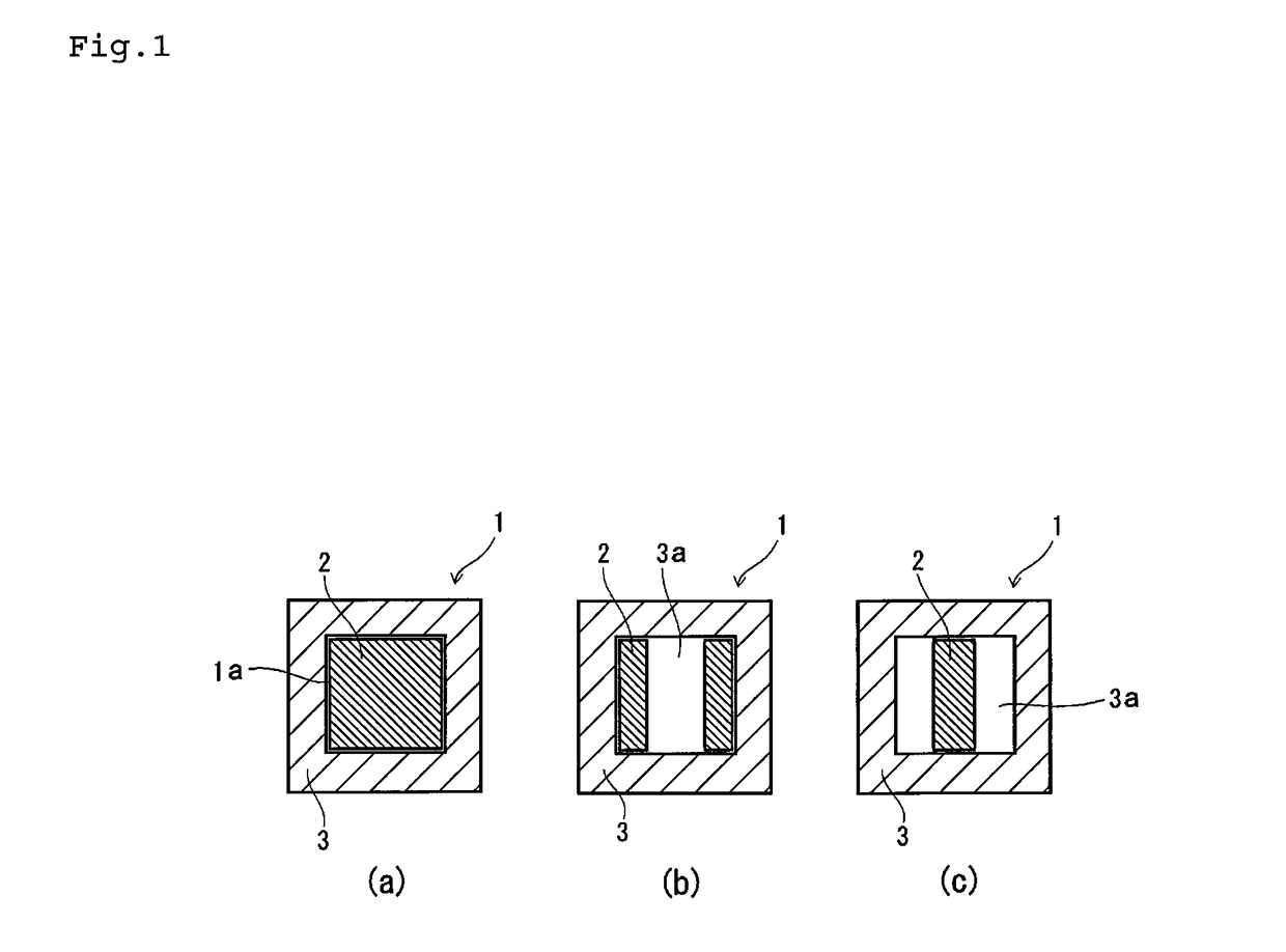
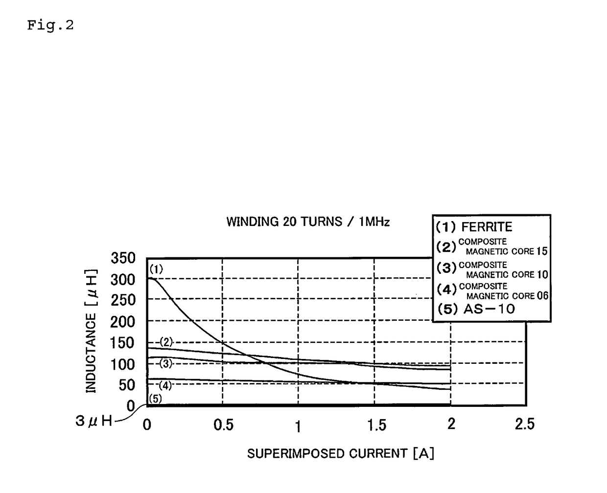
[0031]In the prevailing trend toward a decrease in the size of electrical and electronic equipments, the flow of electric current having higher frequencies through circuits thereof, a ferrite material obtained by a compression molding method which currently prevails in molding methods is superior in its magnetic flux density (magnetic permeability) and inductance value, but inferior in its frequency characteristic and current superimposition characteristic. On the other hand, an injection moldable magnetic material consisting of an amorphous material is superior in its frequency characteristic and current superimposition characteristic, but inferior in its magnetic flux density (magnetic permeability) and inductance value.

[0032]It is possible to form the injection moldable magnetic material for a magnetic core by mixing ferrite powders and amorphous powders with each other. But in this case, it is difficult to adjust the balance between the mechanical strength and magnetic character...


PUM

PropertyMeasurementUnit
heightaaaaaaaaaa
diameteraaaaaaaaaa
diameteraaaaaaaaaa

Abstract

The present invention provides a composite magnetic core, containing magnetic powders poor in its moldability, which can be configured arbitrarily and has a magnetic characteristic excellent in direct current superimposition characteristics and a magnetic element composed of the composite magnetic core and a coil wound around the circumference thereof. A compressed magnetic body (2) obtained by compression-molding magnetic powders is combined with an injection-molded magnetic body (3) obtained by mixing a binding resin with magnetic powders having surfaces thereof electrically insulated and by injection-molding a mixture of the magnetic powders and the binding resin. The compressed magnetic body (2) is press-fitted into the injection-molded magnetic body (3) or bonded thereto at a combining portion thereof to obtain the combined body. The combined body is composed of the injection-molded magnetic body (3) constituting a housing in which the compressed magnetic body (2) is disposed.

Description

TECHNICAL FIELD[0001]The present invention relates to a composite magnetic core and a magnetic element consisting of the composite magnetic core and a coil wound around the circumference thereof.BACKGROUND ART[0002]In recent years, in the prevailing trend toward a decrease in the size of electrical and electronic equipment, the flow of electric current having higher frequencies through circuits thereof, and the application of higher electric current thereto, not only the electrical and electronic equipment but also components of the magnetic core are required to follow the trend in the production thereof. But the characteristic of a ferrite material which presently prevails reaches the limit. Consequently new materials for the magnetic core are being searched for. For example, the ferrite material is being replaced with compressed magnetic materials such as sendusts, amorphous materials, and an amorphous foil band. But the compressed magnetic materials have a poor moldability and a ...

Claims


Application Information

Patent Timeline
Patent Type & Authority Patents(United States)
IPC IPC(8): H01F27/24H01F41/00H01F7/06H01F3/08H01F27/255H01F3/10H01F41/02H01F17/04
CPCH01F3/08H01F3/10H01F17/04H01F27/255H01F41/005H01F41/0246H01F2003/106H01F1/37H01F27/2823
Inventor UEMOTO, IKUOMIYAZAKI, SHINJIHARANO, TAKUJI
Owner NTN CORP
Learn More