
Liquid crystal filling device and liquid crystal panel manufacturing apparatus comprising the same

a filling device and filling technology, applied in non-linear optics, instruments, optics, etc., can solve the problems of affecting the display affecting the viscosity coefficient affecting the quality of the liquid crystal panel, so as to reduce the temperature of the liquid crystal, slow down the diffusion rate of the liquid crystal drop on the substrate, and improve the viscosity coefficient

Active Publication Date: 2017-04-04
BOE TECH GRP CO LTD +1
View PDF10 Cites 0 Cited by
  • Summary
  • Abstract
  • Description
  • Claims
  • Application Information

AI Technical Summary

Benefits of technology

The liquid crystal filling device and the liquid crystal panel manufacturing apparatus provided by this patent decrease the viscosity coefficient of liquid crystal in the device by controlling the temperature, which reduces the possibility of ionic contamination and edge mura / image sticking on the panel, improving display quality.

Problems solved by technology

Accordingly, ionic contamination of liquid crystal may occur due to that the quick diffused liquid crystal is contacted with the sealant not being cured, which causes edge mura and image sticking occurring on the liquid crystal panel.
Furthermore, the display quality of the liquid crystal panel is affected.
However, a height difference will be generated in the color filter substrate at the position of photo spacer or trenching, so that an alignment film may be damaged and a rubbing mark may be generated when the rubbing alignment of the alignment film is performed.
Also, adding photo spacers or trenching will add complexity to process.
Furthermore, if the liquid crystal is dropped onto an array substrate, it is useless to add photo spacers or trenching on the color filter substrate to prevent the liquid crystal from diffusing.

Method used


Image

  • Liquid crystal filling device and liquid crystal panel manufacturing apparatus comprising the same
  • Liquid crystal filling device and liquid crystal panel manufacturing apparatus comprising the same

Examples


Embodiment Construction

[0020]A clear and complete description of technical solutions of the embodiments of the present invention will be given below in combination with the accompanying drawings in the embodiments of the present invention. Apparently, the embodiments described below are merely a part, but not all, of the embodiments of the present invention. All of other embodiments, obtained by a person skilled in the art based on the embodiments of the present invention without any inventive efforts, fall into the protection scope of the present invention.

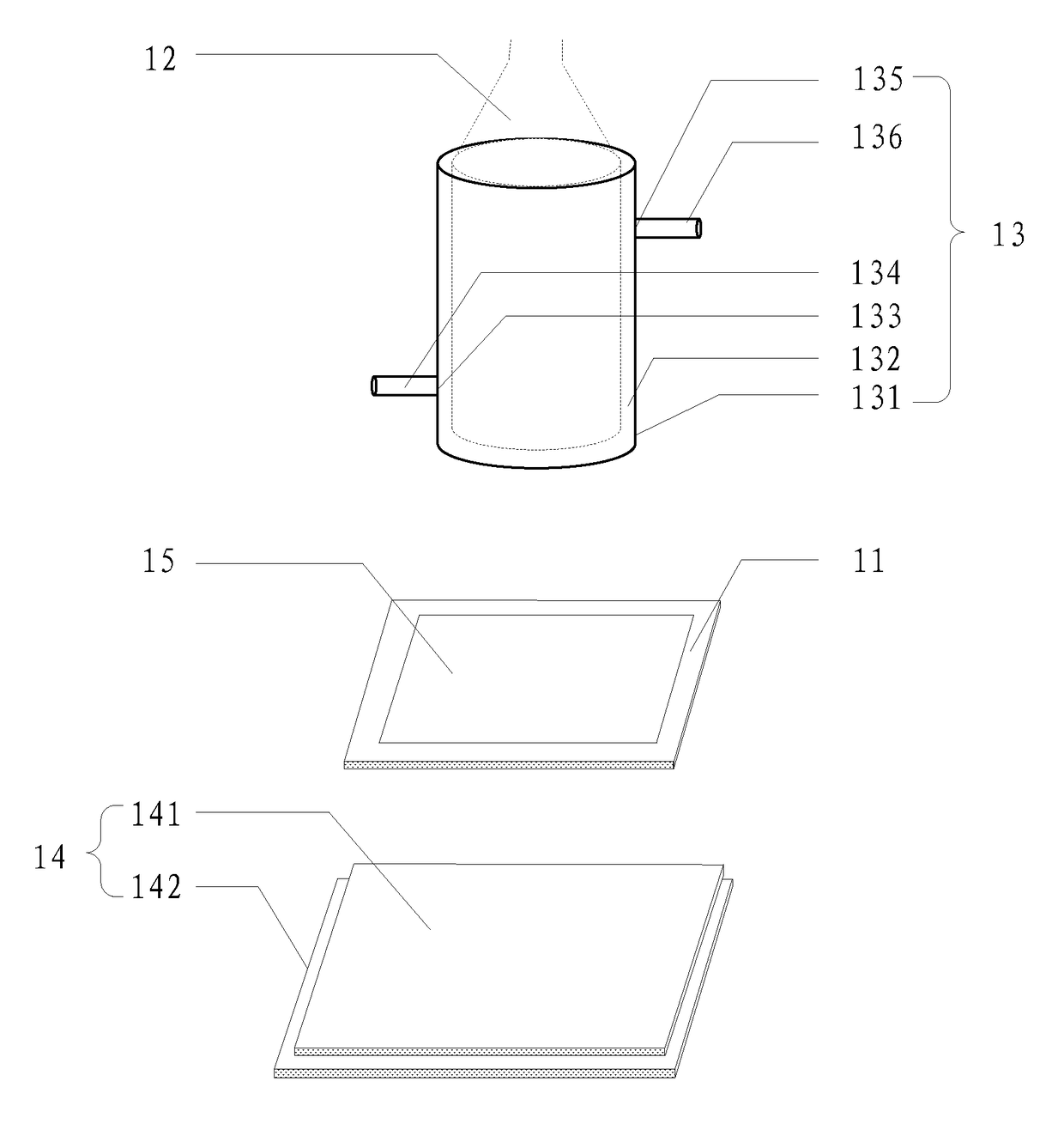
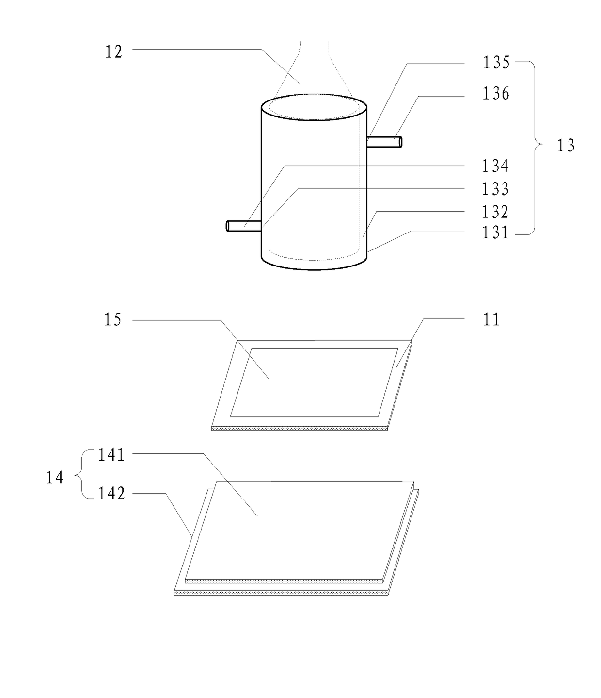
[0021]An embodiment of the present invention provides a liquid crystal filling device, as shown in FIG. 1. The liquid crystal filling device includes a substrate stage 11 and a support (not shown in FIG. 1) used for supporting a liquid crystal container 12. A first temperature adjustment device 13 is provided on the support. The first temperature adjustment device 13 is used to lower the temperature of the liquid crystal in the liquid crystal container...


PUM

PropertyMeasurementUnit
temperatureaaaaaaaaaa
viscosity coefficientaaaaaaaaaa
heightaaaaaaaaaa

Abstract

The present invention relates to the field of liquid crystal panel manufacturing, and provides a liquid crystal filling device and a liquid crystal panel manufacturing apparatus. The technical solutions of the present invention solve the problem of ionic contamination of liquid crystal due to a quick diffusion rate of liquid crystal dropped on a substrate through an existing liquid crystal filling device. In embodiments of the present invention, the liquid crystal filling device includes a substrate stage and a support used for supporting a liquid crystal container. A first temperature adjustment device is provided on the support, which is used to lower the temperature of the liquid crystal in the liquid crystal container, such that the viscosity coefficient of the liquid crystal in the liquid crystal container is increased. The liquid crystal panel manufacturing apparatus includes the above liquid crystal filling device.

Description

CROSS-REFERENCE TO RELATED APPLICATION[0001]This application claims priority under 35 U.S.C. §119 to Chinese Patent Application No. 201410235918.4, filed on May 29, 2014, in the Chinese Intellectual Property Office, the disclosure of which is incorporated by reference herein in its entirety.FIELD OF THE INVENTION[0002]The present invention relates to the field of liquid crystal panel manufacturing, and particularly relates to a liquid crystal filling device and a liquid crystal panel manufacturing apparatus comprising the same.BACKGROUND OF THE INVENTION[0003]In the manufacturing process of a liquid crystal panel, it is required to fill liquid crystal between an array substrate and a color filter substrate through a liquid crystal filling device.[0004]Existing liquid crystal filling devices include a substrate stage and a support used for supporting a liquid crystal container. When filling liquid crystal, a substrate to be filled is mounted on the substrate stage, and the liquid cry...

Claims


Application Information

Patent Timeline
Patent Type & Authority Patents(United States)
IPC IPC(8): G02F1/13G02F1/1333G02F1/1341
CPCG02F1/1303G02F1/1341G02F1/133382
Inventor WANG, CHENLV, FENGZHENZHANG, XINXIAGUO, XIAOXIANG, KANGLV, KUI
Owner BOE TECH GRP CO LTD
Learn More