
Device for reducing pressure pulsations

a technology of pulsation and device, which is applied in the direction of fluid gearings, pipe elements, couplings, etc., can solve the problems of particularly short and compact construction of devices, and achieve the effect of favorable maintenan

Inactive Publication Date: 2017-03-28
FTE AUTOMOTIVE GMBH & CO KG
View PDF21 Cites 2 Cited by
  • Summary
  • Abstract
  • Description
  • Claims
  • Application Information

AI Technical Summary

Benefits of technology

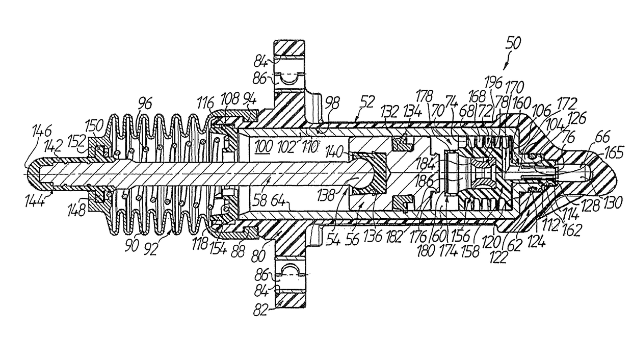
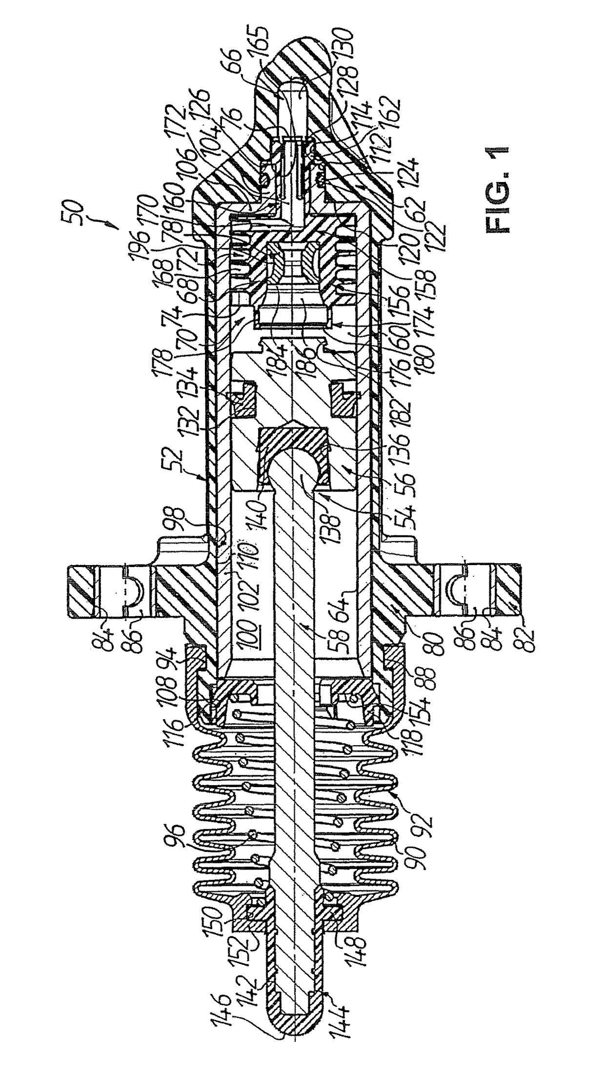
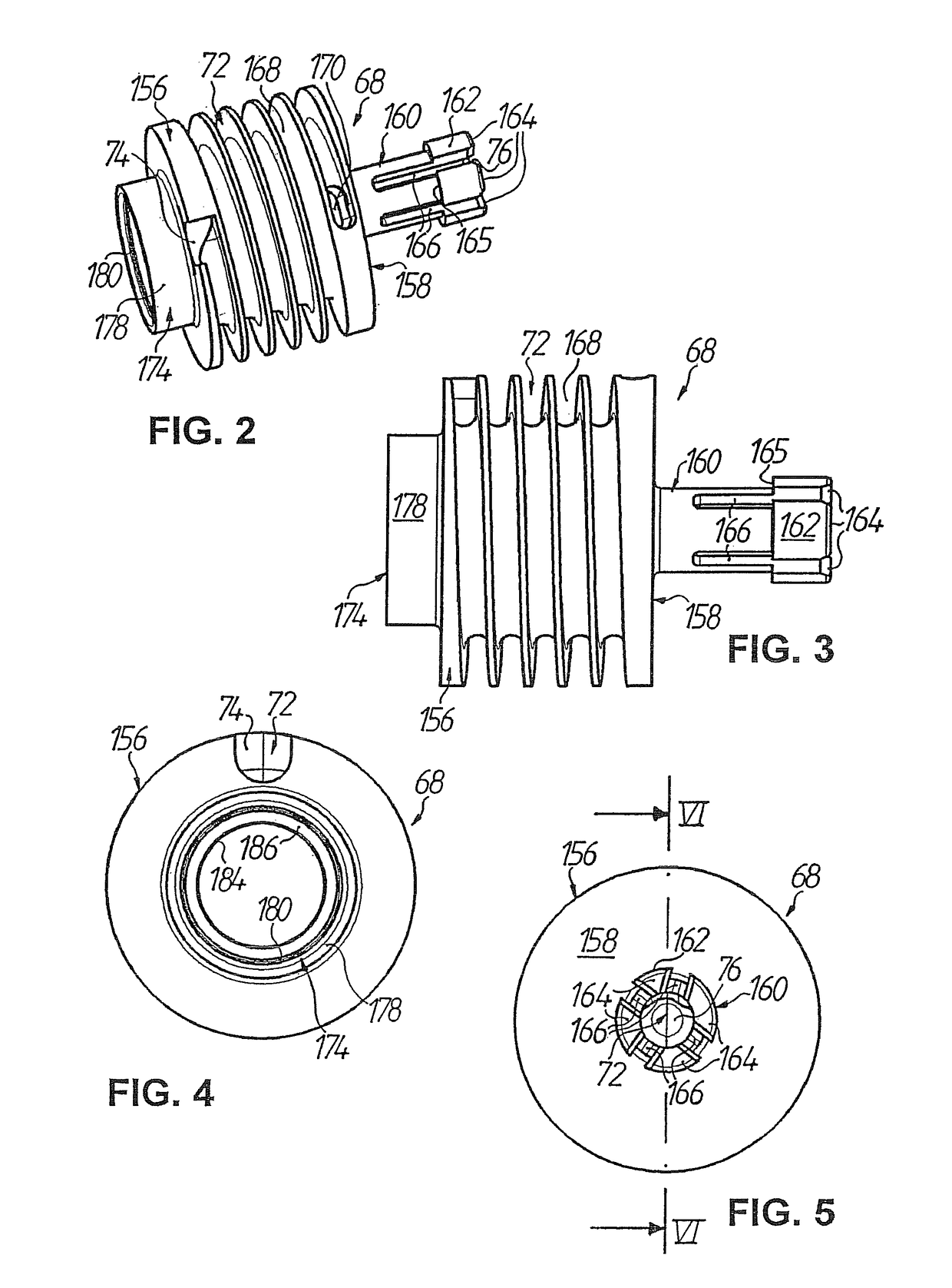
The patent describes a device that can reduce pressure pulsations and vibrations in a hydraulic clutch actuating device. The device uses a combination of two measures: an additional conduit and a volume receiver. This results in highly effective vibration damping. The device is designed to be compact and economical, with the channel and volume receiver placed in the same housing. The device can also be used without needing a narrowed pipe section, which is typically used to reduce vibrations in conventional devices. The helix section in the channel and volume receiver is arranged in a mutually coaxial position, making the device even more compact.

Problems solved by technology

Finally, since the helix section and the volume receiver are arranged in the housing in a mutually coaxial positional relationship with one substantially surrounding the other, the device is of particularly short and compact construction.

Method used


Image

  • Device for reducing pressure pulsations
  • Device for reducing pressure pulsations
  • Device for reducing pressure pulsations

Examples


first embodiment

[0077]As already mentioned in the introduction, the thus-constructed device 70′ for reducing pressure pulsations can be arranged largely freely in the hydraulic line between slave cylinder and master cylinder, for example between a hose section, which is at the slave cylinder side, and a pipe section which is at the master cylinder side, of the hydraulic line. The function or manner of effect of the device 70′ in this regard corresponds with that of the device 70 according to the

[0078]In the case of the third embodiment illustrated in FIGS. 13 to 15 firstly the slave connection 202″ and the master connection 204″ of the two-part housing 200″ are constructed differently from the case of the second embodiment, namely mutually reversed so that the slave connection 202″ is formed as receiving part whilst the slave connection 204″ is constructed as plug part. In this regard the recess 222″ of the slave connection 202″ is in fluid connection with the pressure medium chamber 208″ via a pas...

third embodiment

[0083]Tests were also carried out with respect to the third embodiment, the result of which is illustrated in FIG. 16 by way of example. The actual performance of the test corresponded with that which was already described further above with reference to FIG. 10. However, in the present case use was made of a slave cylinder with an effective piston effective diameter of 19.05 mm and a master cylinder with an effective piston effective diameter of 15.87 mm, which—analogously to FIG. 23—were hydraulically connected together by way of, starting from the slave cylinder, (a) a metallic clutch pipe section (inner diameter: approx. 4.75 mm; wall thickness: approx. 0.7 mm; length: approx. 300 mm), (b) an elastomeric clutch hose section (inner diameter: approx. 6 mm; outer diameter: approx. 12 mm; length: approx. 250 mm, one fabric layer) and (c) a metallic clutch pipe section (inner diameter: approx. 6 mm, wall thickness: approx. 0.7 mm; length: approx. 400 mm) of an existing pressure line ...

second embodiment

[0098]The connecting member 306 itself has, analogously to the second embodiment described in the foregoing with reference to, in particular, FIG. 12, a master connection 204 with receiving geometry known per se, having the recess 222 ending at the opening 76 of the channel 72 at the master cylinder side, the securing element 224 and the insertion slot 226 for that purpose. In addition, the plug end or plug section 304 is provided with an annular groove for reception of an O-ring 318 which seals relative to the second receiving section 302 of the stepped bore 294.

[0099]The insert member 68 bearing against the annular shoulder 320 formed between the first receiving section 298 and the second receiving section 302 of the stepped bore 294 similarly has at the outer circumference of the projection 300 an annular groove 322 (cf. FIG. 21) in which a further O-ring 324 is received, which seals relative to the first receiving section 298 of the stepped bore 294. Finally, the insert member 6...


PUM


Abstract

The invention relates to a device that is always open for the pressure medium for reducing pressure pulsations and that can be switched between a pressure chamber of a slave cylinder and a pressure chamber of a master cylinder of a hydraulic force transmission system for motor vehicles. The device has an additional line section in the form of a channel having an opening on the slave cylinder side, an opening on the master cylinder side, and a channel length equaling a multiple of the direct distance between the two openings, and a volume receiver that can be elastically deformed under pressure, wherein the channel and the volume receiver are combined into an assembly in a housing. The result according to the invention is a device that not only has very good vibration dampening properties, but is also very compact and has a cost-effective design.

Description

TECHNICAL FIELD[0001]The present invention relates to a device for reducing pressure pulsations, the device being connectible between a pressure chamber of a slave cylinder and a pressure chamber of a master cylinder of a hydraulic force transmission system and being constantly open to the pressure medium. In particular, the invention relates to such devices for reducing pressure pulsations, such as are used on a large scale in hydraulic clutch actuating devices for motor vehicles.PRIOR ART[0002]FIG. 23 shows a conventional hydraulic clutch actuating device 10 for motor vehicles in a simplified illustration. The hydraulic clutch actuating device 10 comprises a master cylinder 12, which is mounted on a pedal block 11 of the motor vehicle, and a slave cylinder mounted in the motor vehicle in the vicinity of a transmission, the cylinders being hydraulically interconnected by way of a hydraulic line 16 which in this case starts has, seen from the master cylinder 12, a first pipe section...

Claims


Application Information

Patent Timeline
Patent Type & Authority Patents(United States)
IPC IPC(8): F16D48/02F16D25/08F15B21/00
CPCF16D25/088F15B21/008F16D2048/0215F16L55/041F16D2300/22F16D25/14F16H47/02F15B21/04
Inventor GEBERT, STEFANMACHT, EGIDMARKS, PAULMUELLER, ROBERTRYBA, JUERGENSCHNEIER, JOCHENWEIBELZAHL, WILFRIED
Owner FTE AUTOMOTIVE GMBH & CO KG
Learn More