
Method and device for controlling an internal combustion engine with a variable compression ratio

a compression ratio and internal combustion engine technology, applied in the direction of electric control, mechanical control, machines/engines, etc., can solve the problems of only realizing the adjustment itself, only achieving the limited actuation speed of the adjustment device, and increasing the fuel consumption, so as to reduce the fuel compensation

Active Publication Date: 2017-03-21
AUDI AG
View PDF14 Cites 2 Cited by
  • Summary
  • Abstract
  • Description
  • Claims
  • Application Information

AI Technical Summary

Benefits of technology

The invention proposes a method to operate an internal combustion engine by adjusting the compression ratio to an optimal value based on the actual load torque of the engine. This allows for a rapid change of the operating point or load torque, reducing fuel compensation. The method uses an estimated operating variable, which is determined regularly during operation in a predictive operating mode. The gradient of the operating variable is determined and the predictive operating mode is terminated if the gradient exceeds a threshold value. This prevents inaccurate predictions and ensures a smooth transition to the normal operating mode. The method also includes a hysteresis-like behavior to avoid constant changes between the normal operating mode and the predictive operating mode. Overall, the method improves fuel efficiency and engine performance.

Problems solved by technology

Hereby, however, the adjustment device only achieves a limited actuating speed.
However, due to the limited actuating speed the adjustment itself can only be realized with a higher fuel consumption.
When the operating point changes or the load torque changes slowly, this is unproblematic because the actuating speed of the adjustment device is sufficient.
In particular, the setpoint compression ratio is only determined from the operating variable of the internal combustion engine after reaching the new operating point and is subsequently set by the adjustment device thus leading to a significant time delay between the actual compression ratio and the optimal compression ratio.

Method used


Image

  • Method and device for controlling an internal combustion engine with a variable compression ratio
  • Method and device for controlling an internal combustion engine with a variable compression ratio

Examples


Embodiment Construction

[0024]In the following, the invention is described on the basis of the exemplary embodiments shown in the drawing without limiting the invention. It is shown in:

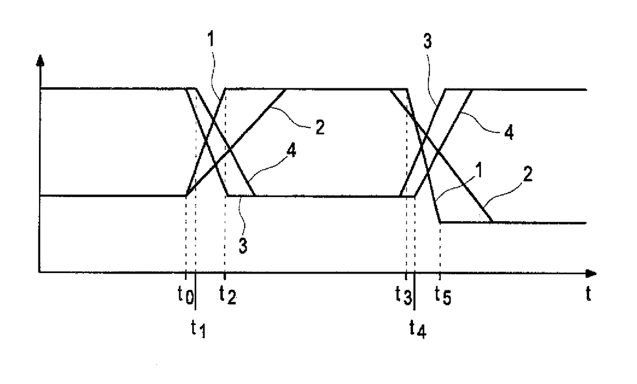
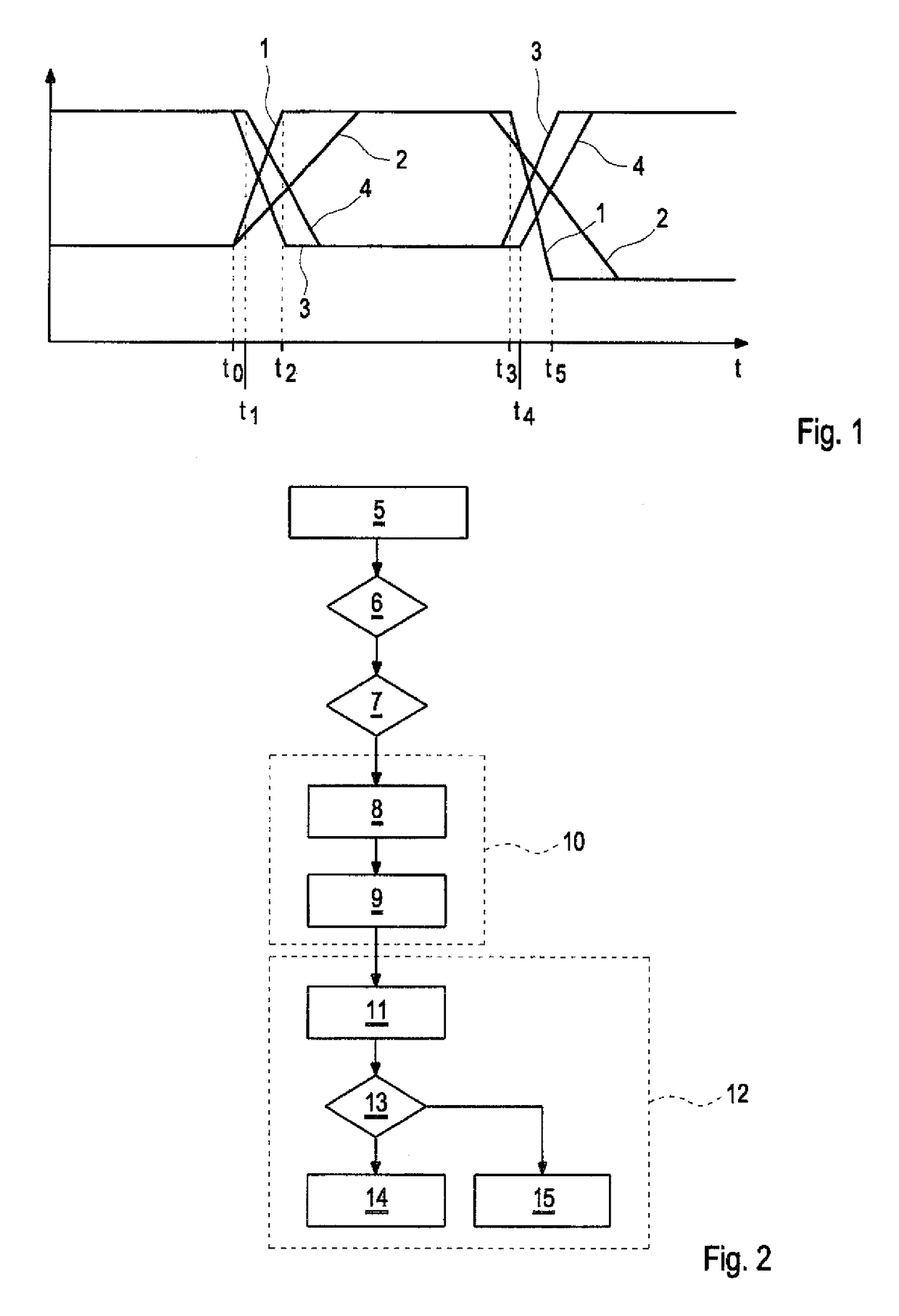
[0025]FIG. 1 a diagram in which an operating element variable, a load torque of an internal combustion engine, a setpoint compression ratio as well as an actual compression ratio over time are shown, and

[0026]FIG. 2 a process diagram of a method to operate a internal combustion engine with a variable compression ratio.

DETAILED DESCRIPTION OF PREFERRED EMBODIMENTS

[0027]FIG. 1 shows a diagram in which different variables are plotted over the time t. A course 1 shows the course of an operating element variable, wherein the operating element variable reflects the position of an operating element of a motor vehicle, namely for example an acceleration pedal. It can be seen that a driver of the motor vehicle changes the position of the acceleration pedal at the time point t0 to achieve or compensate a higher load torque of the inte...


PUM


Abstract

In a method for operating an internal combustion engine a compression ratio is set to a setpoint compression ratio by means of an adjustment device, wherein in a normal operating mode of the internal combustion engine the setpoint compression ratio is determined as a function of an, operating variable of the internal combustion engine. The internal combustion engine is at least temporarily operated in a predictive operating mode in which the setpoint compression ratio is determined on the basis of an anticipated estimated operating variable which is estimated on the basis of the instantaneous gradient of the operating variable over time.

Description

CROSS-REFERENCES TO RELATED APPLICATIONS[0001]This application is the U.S. National Stage of International Application No. PCT / EP2014 / 000146, filed Jan. 21, 2014, which designated the United States and has been published as International Publication No. WO 2014 / 114442 and which claims the priority of German Patent Application, Serial No. 10 2013 001 043.8, filed Jan. 22, 2013, pursuant to 35 U.S.C. 119(a)-(d).BACKGROUND OF THE INVENTION[0002]The present invention relates to a method for operating a internal combustion engine, in which a compression ratio is set to a setpoint compression ratio by means of an adjustment device, wherein in a normal operating mode of the internal combustion engine the setpoint compression ratio is determined as a function of an operating variable of the internal combustion engine. The invention further relates to a internal combustion engine.[0003]The internal combustion engine serves for example to drive a motor vehicle. The internal combustion engine ...

Claims


Application Information

Patent Timeline
IPC IPC(8): F02B75/04F02D41/04F02D15/00F02D41/14
CPCF02D15/00F02D41/04F02D2041/1412F02D2200/1002F02D2200/1004F02D2700/03
Inventor AZADEH, REZA
Owner AUDI AG
Learn More