
Method for diagnosing an exhaust gas catalytic converter, diagnosis device and motor vehicle having such a device

a technology of exhaust gas catalytic converter and diagnosis device, which is applied in the direction of electric control, instruments, machines/engines, etc., can solve the problem that the exhaust gas recirculation is not sufficient to meet the requirements, and achieve the effect of improving precision

Active Publication Date: 2017-03-14
VOLKSWAGEN AG
View PDF27 Cites 5 Cited by
  • Summary
  • Abstract
  • Description
  • Claims
  • Application Information

AI Technical Summary

Benefits of technology

The invention relates to a new method for diagnosing the performance of exhaust-gas catalytic converters in vehicles. Unlike conventional methods, this method measures the concentration of exhaust-gas components upstream from the converter, using a sensor located close to the engine. This allows for more frequent and precise diagnostics, especially for defective catalysts. The method also involves using an oxidation catalytic converter to increase the ratio of NO2 to NO in the exhaust gas, which improves the conversion rate of the downstream SCR catalytic converter. Overall, this method provides greater accuracy and reliability for diagnosing the performance of exhaust-gas catalytic converters.

Problems solved by technology

As a rule, however, exhaust-gas recirculation is not sufficient to comply with statutory NOx limit values, which is why there is an additional need for an active exhaust-gas after-treatment that lowers the NOx end emission by catalytically reducing NOx to form nitrogen N2.

Method used


Image

  • Method for diagnosing an exhaust gas catalytic converter, diagnosis device and motor vehicle having such a device
  • Method for diagnosing an exhaust gas catalytic converter, diagnosis device and motor vehicle having such a device
  • Method for diagnosing an exhaust gas catalytic converter, diagnosis device and motor vehicle having such a device

Examples


Embodiment Construction

[0032]The invention will be presented below on the basis of an example of an SCR catalytic converter. However, it goes without saying that the invention can also be employed for other exhaust-gas catalytic converters.

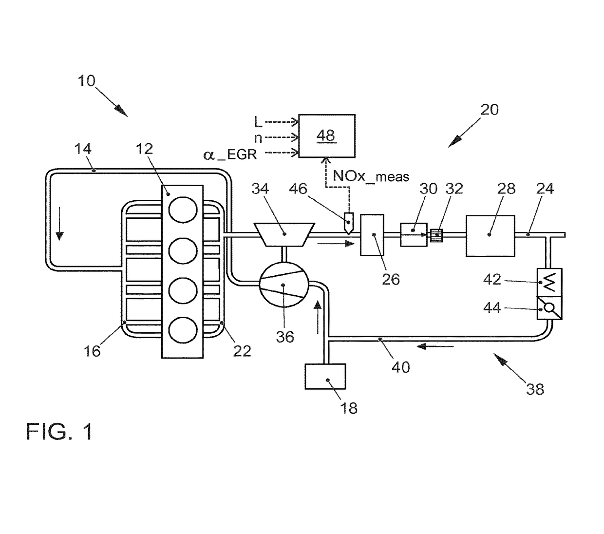
[0033]FIG. 1 shows a drawing of a motor vehicle which is designated in its entirety by the reference numeral 10 and which is driven by an internal combustion engine 12 that is lean-running, at least at times, especially by a diesel engine that serves as the source of traction. The internal combustion engine 12 here has, for instance, four cylinders, whereby any number of cylinders diverging from this is likewise possible.

[0034]The internal combustion engine 12 is supplied with combustion air via an air line 14 and via an air manifold 16 that conveys the drawn-in air to the cylinders. The combustion air drawn in from the ambient air is cleaned of particulate constituents by means of an air filter 18.

[0035]The motor vehicle 10 also has an exhaust-gas system which is desig...


PUM


Abstract

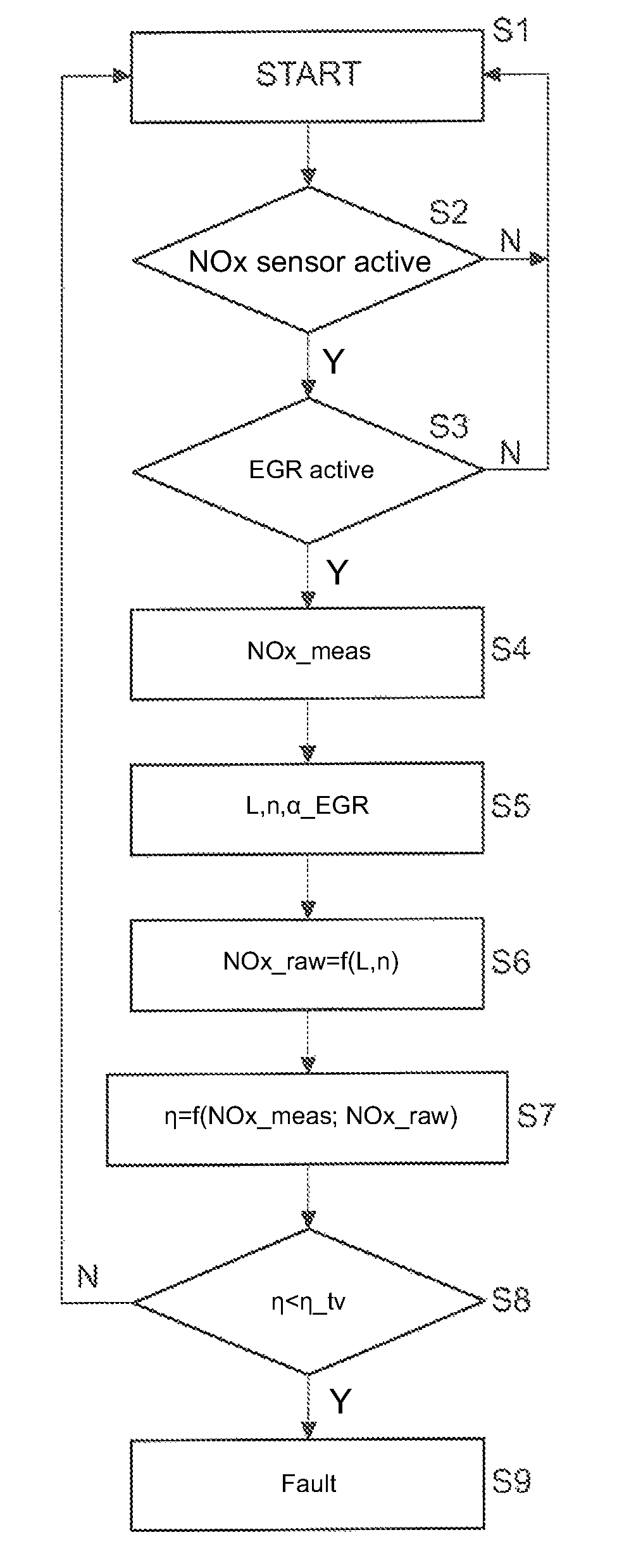
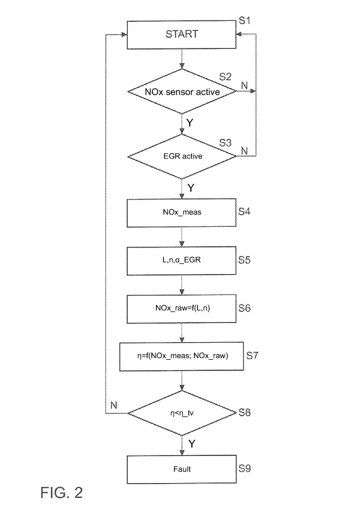
A method for diagnosing an exhaust-gas catalytic converter (28) arranged in an exhaust-gas system (20) of an internal combustion engine (12) for the catalytic conversion of at least one exhaust-gas component from the internal combustion engine (12), which has an exhaust-gas recirculation means with which a partial stream of the exhaust gas can be drawn off downstream of the catalytic converter (14) and fed into the combustion air of the internal combustion engine (12), involves determining the current raw emission (NOx—raw) of the internal combustion engine (12) in of the exhaust-gas component; measuring the current concentration of the exhaust-gas component (NOx—meas) in the exhaust gas upstream of the catalytic converter (28); and determining a diagnostic value for the catalytic converter (28) in terms of the conversion of the exhaust-gas component as a function of the modelled raw emission (NOx—raw) from the internal combustion engine (12) and the measured concentration of the exhaust-gas component (NOx—meas). The invention further relates to a diagnostic device configured to perform the method and a motor vehicle having such a device.

Description

CROSS-REFERENCE TO RELATED APPLICATIONS[0001]This application is a National Phase Application of PCT International Application No. PCT / EP2013 / 074351, International Filing Date Nov. 21, 2013, claiming priority of German Patent Application No. 10 2012 025 002.9, filed Dec. 20, 2012, each of which is hereby incorporated by reference in its entirety.FIELD OF THE INVENTION[0002]The invention relates to a method for diagnosing an exhaust-gas catalytic converter arranged in the exhaust-gas system of the internal combustion engine for the catalytic conversion of at least one exhaust-gas component of an internal combustion engine; the invention also relates to a diagnostic device that is configured to carry out said method, and to a motor vehicle having such a diagnostic device. In a special embodiment, the exhaust-gas catalytic converter is a catalytic converter that functions according to the principle of selective catalytic reduction for purposes of reducing nitrogen oxide NOx.BACKGROUND ...

Claims


Application Information

Patent Timeline
Patent Type & Authority Patents(United States)
IPC IPC(8): G01M17/00F01N11/00G06F19/00F01N3/20F01N9/00F01N3/08F01N3/10
CPCF01N11/007F01N3/2066F01N11/00F01N3/0842F01N3/101F01N3/103F01N9/005F01N2340/02F01N2550/02F01N2560/026F01N2900/0412F01N2900/1402F01N2900/1621F02M26/06F02M26/28Y02T10/22Y02T10/24Y02T10/47F02D41/0072F02D41/0235F02D41/1461F02D41/1462Y02A50/20Y02T10/12Y02T10/40
Inventor VELDTEN, BURKHARDKULASZEWSKI, MACIEJ
Owner VOLKSWAGEN AG
Learn More