X-ray CT apparatus and tomography method
a technology of x-ray ct and tomography, which is applied in the field of x-ray ct apparatus or x-ray tomography method thereof, can solve the problems of increasing the amount of image noise in the reconstructed image, and the visibility of a lesion or the like, and achieves the effect of little image quality degradation
- Summary
- Abstract
- Description
- Claims
- Application Information
AI Technical Summary
Benefits of technology
Problems solved by technology
Method used
Image
Examples
first embodiment
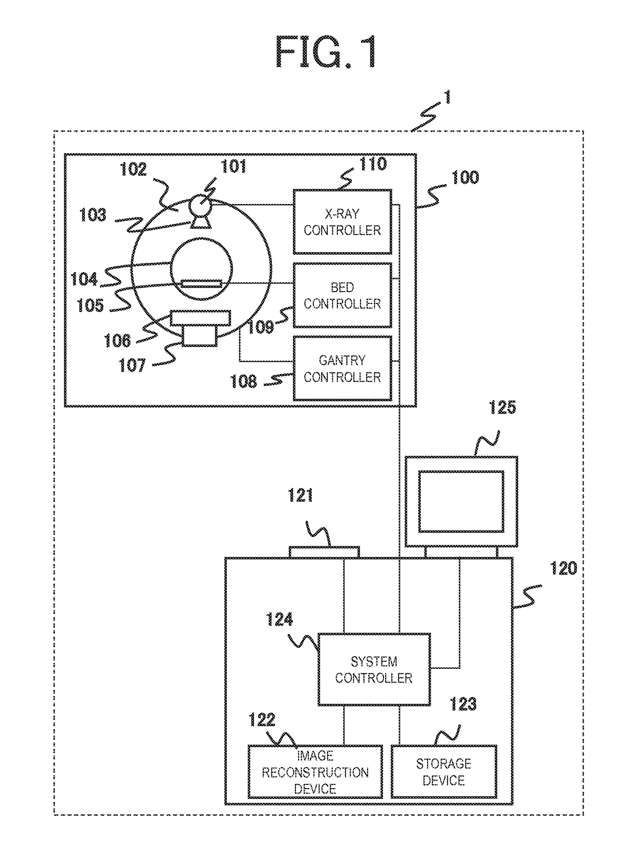
[0044]FIG. 1 is a diagram showing the overall configuration of an X-ray CT apparatus 1 that is an embodiment. The X-ray CT apparatus 1 includes a scan gantry unit 100 and a console 120.
[0045]The scan gantry unit 100 includes an X-ray tube 101, a rotary disk 102, a collimator 103, an X-ray detector 106, a data collection device 107, a bed 105, a gantry controller 108, a bed controller 109, and an X-ray controller 110. The X-ray tube 101 is a device for irradiating an object placed on the bed 105 with X-rays. The collimator 103 includes a mechanism for limiting the emission range of X-rays emitted from the X-ray tube 101 or an X-ray compensation filter for adjusting the dose distribution of X-rays. The rotary disk 102 includes an opening 104 through which the object placed on the bed 105 is inserted and also includes the X-ray tube 101, the X-ray detector 106, and the data collection device 107 mounted therein, and rotates around the object. The rotary disk 102 serves as a rotation me...
second embodiment
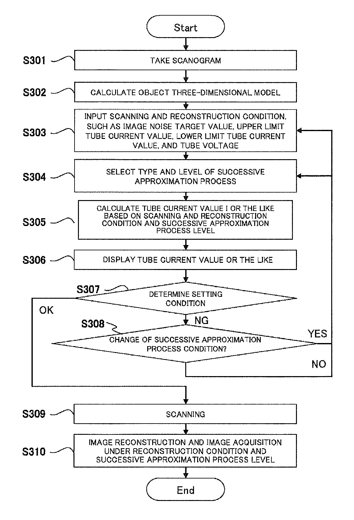
[0142]FIG. 17 is a diagram showing an operation according to a second embodiment of the present invention. Steps denoted by the same reference numerals as in FIG. 3 are approximately the same operations. Differences from the first embodiment shown in FIG. 3 are that a recommended condition is presented to the operator in step S311. As an example, conditions regarding the setting of the successive approximation process level and the setting of the image noise target value will be described as a recommended condition for the SD mode. A recommended condition for the CNR mode can also be similarly set. Hereinafter, step S311 will be described in detail. Since other steps are the same as in FIG. 3, explanation thereof will be omitted.
[0143]In step S307 of FIG. 17, it is determined from an input instruction or the like whether or not the current value of the X-ray tube 101 or the like displayed in the previous step S306 is an acceptable value. For example, when the predicted image noise v...
third embodiment
[0155]FIG. 21 is a diagram showing an operation according to a third embodiment of the present invention. Steps denoted by the same reference numerals as in the first embodiment shown in FIG. 3 indicate approximately the same operations. Differences from the first and second embodiments are that the successive approximation process level that can be selected in step S314 is limited in the present embodiment while any successive approximation process level is selected in step S304 in the first and second embodiments. In the second embodiment, a recommended condition is displayed in order to avoid clipping of the tube current, and these are displayed after the tube current value of the X-ray tube is calculated. In the present embodiment, however, the recommended condition is displayed when selecting the successive approximation process level before the tube current value of the X-ray tube is calculated. Hereinafter, it is assumed that N levels of Li (i=1, 2, . . . , N) are prepared as...
PUM
 Abstract
Description
Claims
Application Information
 - R&D
- Intellectual Property
- Life Sciences
- Materials
- Tech Scout
- Unparalleled Data Quality
- Higher Quality Content
- 60% Fewer Hallucinations
Browse by: Latest US Patents, China's latest patents, Technical Efficacy Thesaurus, Application Domain, Technology Topic, Popular Technical Reports.
© 2025 PatSnap. All rights reserved.Legal|Privacy policy|Modern Slavery Act Transparency Statement|Sitemap|About US| Contact US: help@patsnap.com


