
Analyais and control of aerosol output

an aerosol and output technology, applied in the field of aerosol output analysis, can solve the problems requiring optical system and air flow measurement system, and not being able to achieve the effect of reducing the reliability of density measuremen

Inactive Publication Date: 2017-03-07
KONINKLJIJKE PHILIPS NV
View PDF16 Cites 7 Cited by
  • Summary
  • Abstract
  • Description
  • Claims
  • Application Information

AI Technical Summary

Problems solved by technology

The method described above of estimating the aerosol output rate from optical beam obscuration and air flow has the disadvantage that two detection systems are required: the optical system and the air flow measurement system.
This reduces the reliability of the density measurement, because it is not possible to distinguish if the signal decrease is caused by the aerosol density or the contamination of the optics.
Since the mouthpiece is usually a detachable and replaceable part of a nebulizer, the location of the optical system may create design difficulties and increasing costs.
For an optical system close to the mesh, it is possible to construct the optical system in such a way that contamination is to a large extent avoided, but the disadvantage is that the average velocity of the droplets close to the mesh is defined by the aerosol generation system instead of the air flow.
As a result, the density of the aerosol beam (as detected by the optical system) increases only marginally with the aerosol output rate, and cannot be used as reliable estimate of the aerosol output rate.
This is a computationally intensive and hardware intensive process.

Method used


Image

  • Analyais and control of aerosol output
  • Analyais and control of aerosol output
  • Analyais and control of aerosol output

Examples


Embodiment Construction

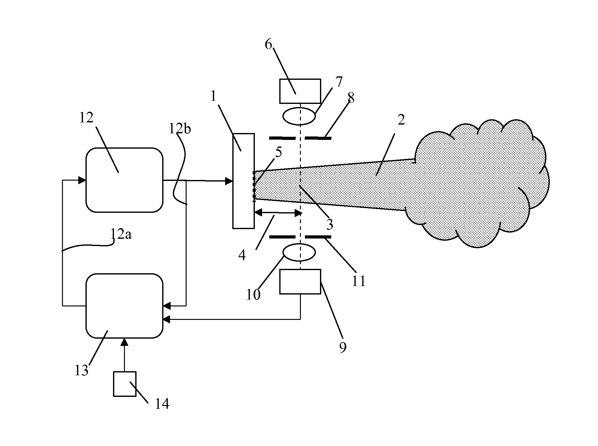
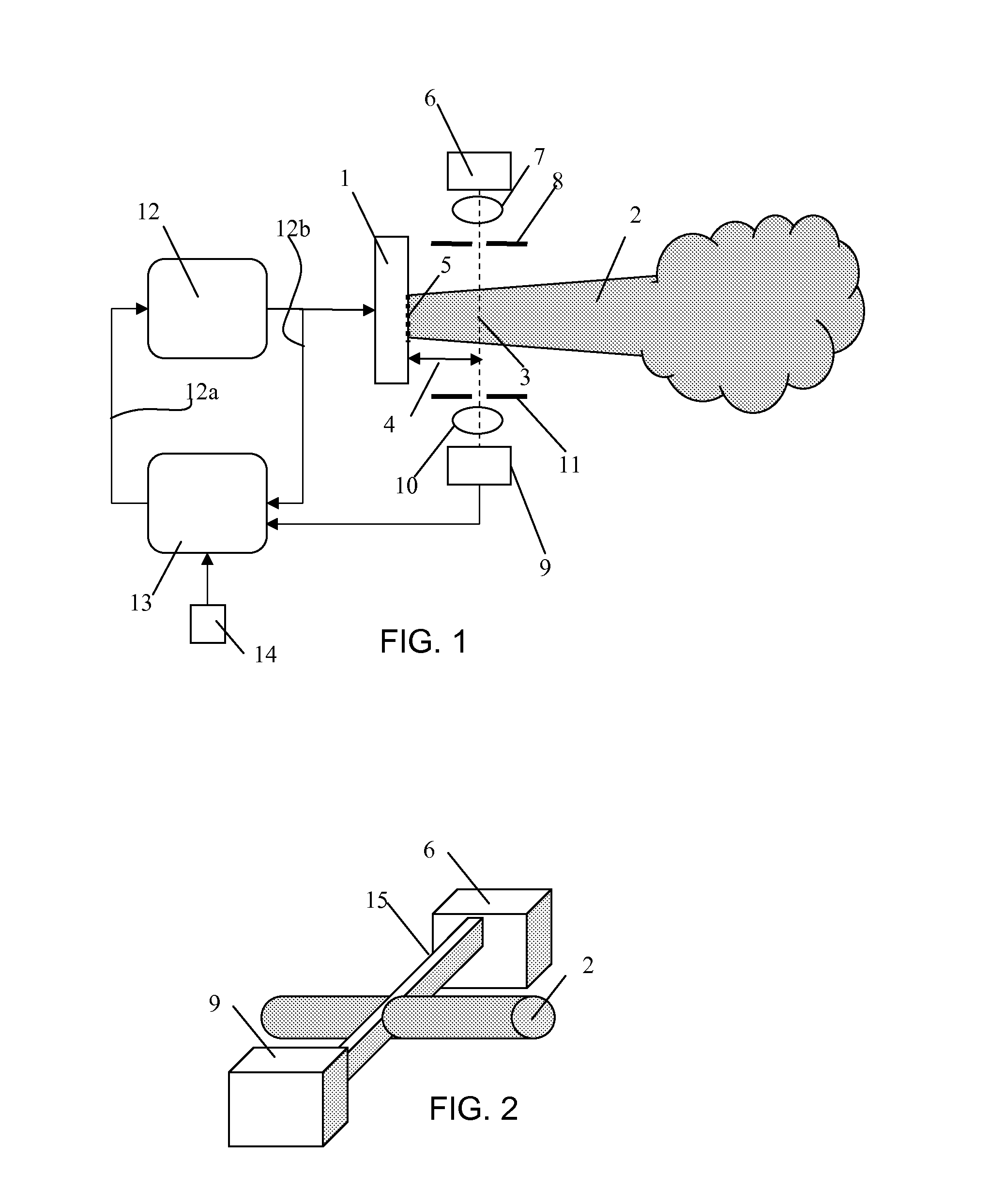
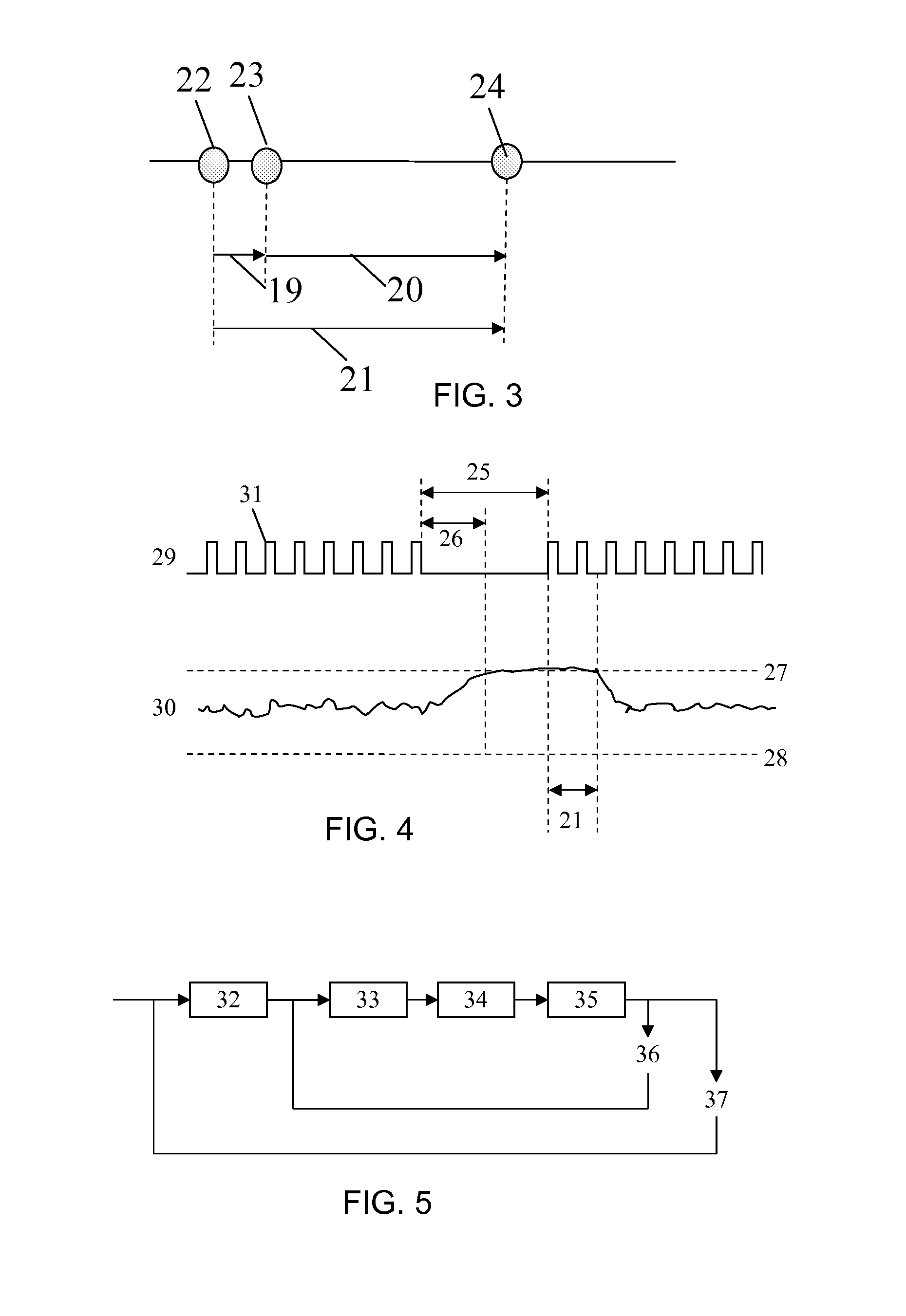
[0041]The invention provides an aerosol generation system in which a conventional aerosol density detector is used. A time delay measurement device is adapted to derive a timing measurement based on a generator drive signal and the aerosol density detector output. The timing measurement is indicative of a time delay between the aerosol generation and the presence of the generated aerosol at the aerosol density detector, which is at a known distance from the aerosol generator. The timing measurement (which is related to the aerosol velocity) and the aerosol density are combined to derive an aerosol output rate, i.e. the mass transport rate. The aerosol output rate can be used as part of a feedback control mechanism.

[0042]FIG. 1 shows a nebulizer system of the invention, with a piezoelectric driven aerosol generation system 1 that generates aerosol 2 using a mesh 5. An optical system generates a beam 3 at distance 4 from the mesh 5. The optical system consists of a light source 6 with...


PUM

PropertyMeasurementUnit
volumeaaaaaaaaaa
time delay measurementaaaaaaaaaa

Abstract

An aerosol generation system (and method) comprises an aerosol generating device (1) for generating an aerosol output (2) and controller (12) for controlling the generating device (1) using a generator drive signal. An aerosol density detector (6,9) is used. A time delay measurement device (13) is adapted to derive a timing measurement based on the generator drive signal and the aerosol density detector output, wherein the timing measurement and the aerosol density are combined to derive an aerosol output rate.

Description

CROSS-REFERENCE TO PRIOR APPLICATIONS[0001]This application is the U.S. National Phase application under 35 U.S.C. §371 of International Application Serial No. PCT / IB2012 / 054683, filed on Sep. 10, 2012, which claims the benefit of U.S. Application Ser. No. 61 / 536,107, filed on Sep. 19, 2011. These applications are hereby incorporated by reference herein.FIELD OF THE INVENTION[0002]This invention relates to the analysis of an aerosol output.BACKGROUND OF THE INVENTION[0003]Nebulizers generate an aerosol output, and are used for medication delivery through the respiratory channel. The patient receives a specific amount of medication in the form of small droplets (aerosol) that are formed by forcing the medication through a mesh in the form of a thin metal plate with tiny holes.[0004]The volume of medication to be nebulized (typically 0.2 to 2 ml) is dosed into the device, and the device generates the aerosol by means of well known methods such as a vibrating mesh, vibrating horn, or a...

Claims


Application Information

Patent Timeline
Patent Type & Authority Patents(United States)
IPC IPC(8): B05B12/08A61M11/00A61M15/00G01N15/06B05B17/06B05B12/00G01F1/74G01F1/86G01N15/00B05B17/00
CPCB05B12/082A61M11/005A61M15/0085B05B12/006B05B17/0607G01F1/74G01F1/86G01N15/06A61M2205/3306A61M2205/3379B05B17/0646G01N2015/0026G01N2015/0693
Inventor BENTVELSEN, PETER HENRICUS CORNELIUSVAN DER MARK, MARTINUE BERNARDUSHUIJGEN, HENDRIK
Owner KONINKLJIJKE PHILIPS NV
Learn More