
Exercise device

a technology of exercise equipment and load, which is applied in the direction of muscle exercise equipment, sport apparatus, weights, etc., can solve the problems of increasing the time necessary for load adjustment, low reliability, and complicated load adjustmen

Active Publication Date: 2017-03-07
MARKELOV VADIM EVGENEVICH
View PDF23 Cites 1 Cited by
  • Summary
  • Abstract
  • Description
  • Claims
  • Application Information

AI Technical Summary

Benefits of technology

Enhances safety by preventing unintended weight shifts and allows quick, easy load adjustment, ensuring stability and reducing the risk of device overturning, making it suitable for outdoor use across various exercises and seasons.

Problems solved by technology

The drawbacks of this prior art device consist in low reliability and complicated adjusting of the load due to employment of the rope-and-pulley system.
The drawback of this prior art exercise device consists in that, in order to adjust the load applied to the levers, it is necessary to take off or to load some weight elements, wherein such adjustment of the load shall be performed at two sides of the exercise device.
Another drawback is constituted by necessity of fixing the weight elements, mounted on both sides, with the locks, which increases the time necessary for adjustment of the load and, therefore, decreases the time available for exercising.
Moreover, there exists a possibility of dropping one or more of weight elements in the course of removing or installing them, which is disadvantageous for safety of the exercising person.
This exercise device may be employed in open out-of-door areas; however, it is not free from certain drawbacks.
However, no limiter to limit an uppermost position of the levers is provided in the structure of the device.
Therefore, overturning of the lever bearing the weight may take place if it is lifted by an exercising person up to a certain position.
If, in result, a center of gravity of the weight passes over the axle of the support frame to be located to the left of this axle, a self-induced overturning of the lever with the weight can follow, which may result in hurting an exercising person.
Another disadvantage consists in inability of adjusting the load applied to the handle of the lever as a known percentage ratio of the employed weight, so that the exercising person is unable to perform the adjustment of the load easily and quickly.

Method used


Image

  • Exercise device
  • Exercise device
  • Exercise device

Examples


Embodiment Construction

[0019]The proposed technical solution will be further described with a reference to a particular embodiment thereof clearly demonstrating capability to attain the target technical result by means of the above-indicated entirety of essential features.

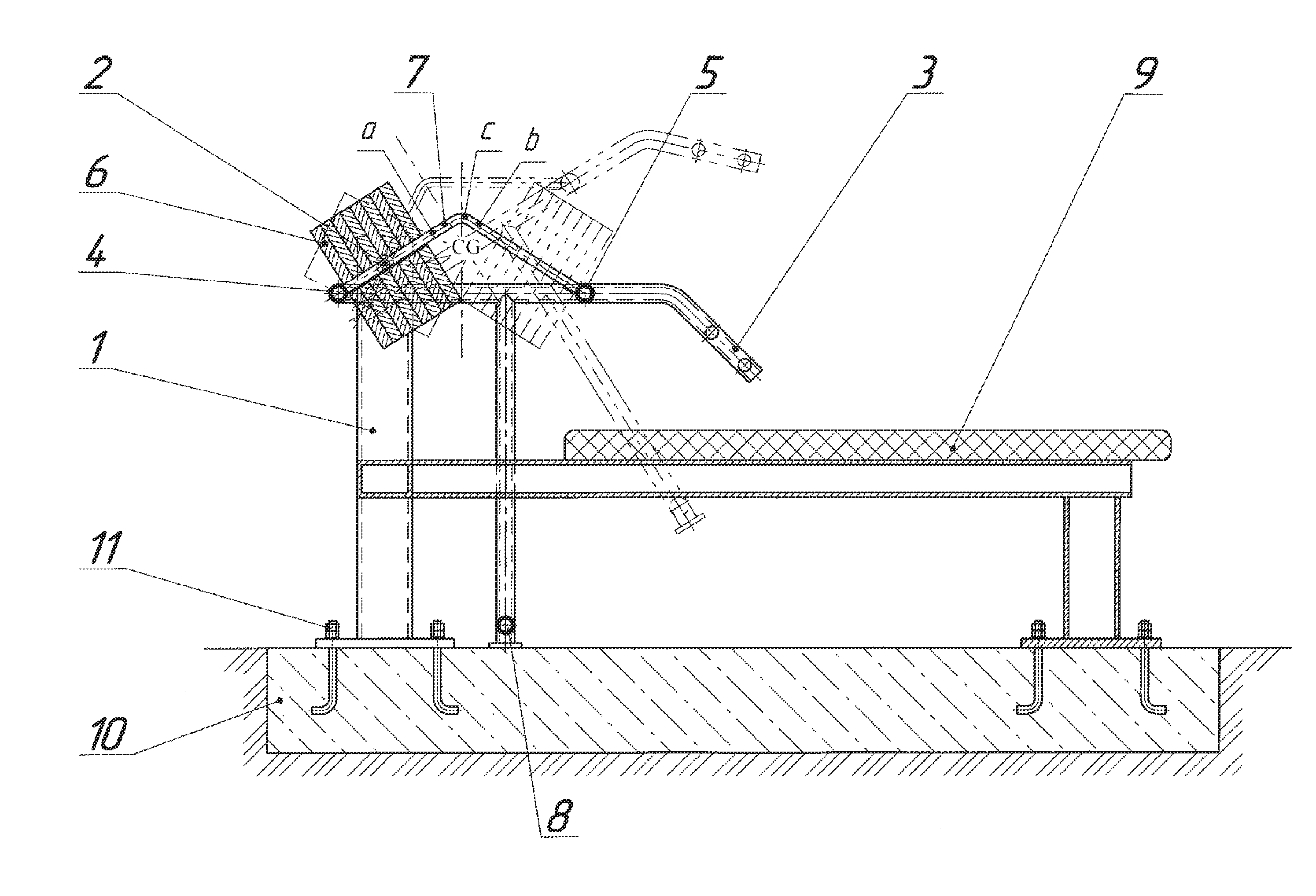
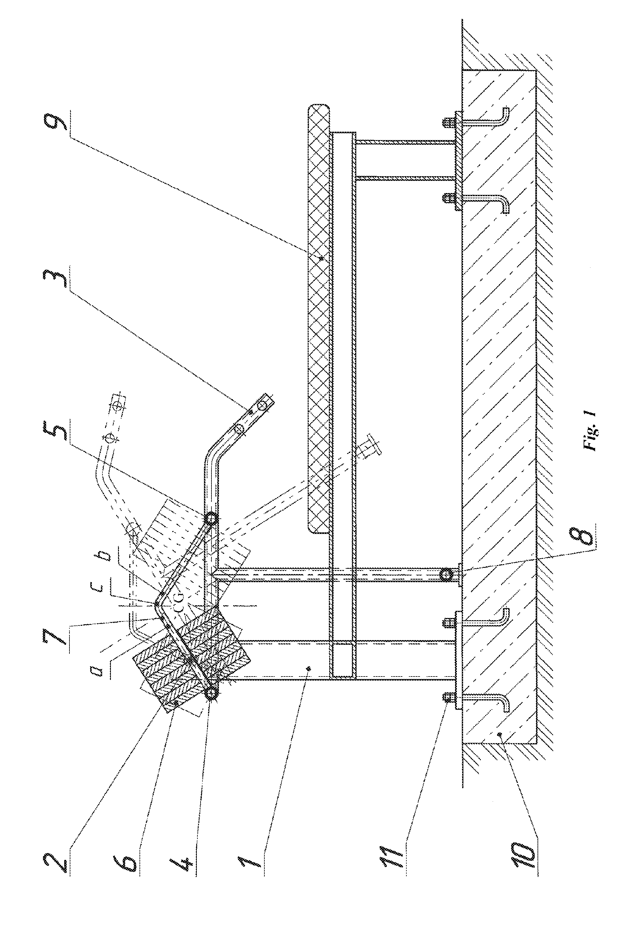
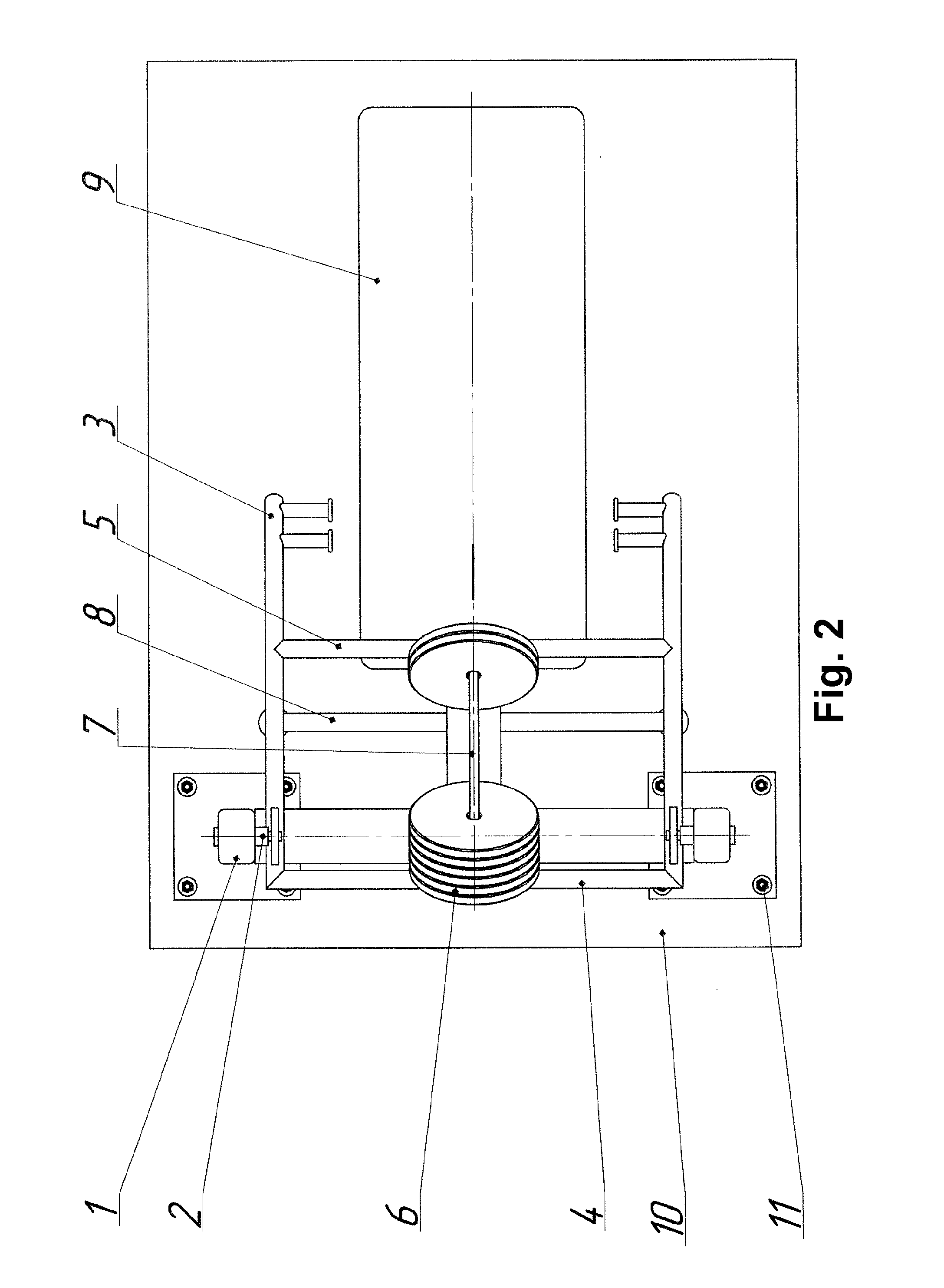
[0020]In accordance with the technical solution (see FIGS. 1 and 2), an exercise device includes a support frame 1 with an axle 2. The axle 2 consists of two coaxial half-axles (not denoted in FIG. 1) positioned at the outer side of the levers 3. The latter are pivotally mounted to uprights, or posts, (not denoted in FIG. 1) of the support frame 1. Limiters, or stoppers 4 and 5 for limiting the movement of weight elements 6 are formed as transverse members located between the levers 3 and located on both sides of the axle 2. Guide member 7 for the weight elements, which is arranged between limiters 4 and 5, is formed as a bent rod having two rectilinear portions a and b connected by a rounded corner, or an arc c. The guide member 7 is in...


PUM


Abstract

An exercise machine in the form of a stationary rigid metal construction is provided, which includes a support frame having an axle. The axle is provided on the outer side of levers. The levers are pivotally mounted on the uprights of the support frame. Limiters for limiting the movement of a weight are in the form of transverse connections between the levers and are installed on both sides of the axle. A load guide is provided between the limiters and is in the form of a bent rod having two rectilinear portions and an arc. A limiter of lever position is in the form of a U-shaped frame and is affixed to the levers. A bench is mounted on the support frame.

Description

CROSS REFERENCE TO RELATED APPLICATIONS[0001]The present application is a U.S. National Phase of International Patent Application PCT / RU2013 / 001197, filed Dec. 30, 2013, which claims priority to Russian Application No. 2013103874, filed on Jan. 29, 2013, the entire contents of which are incorporated herein by reference.FIELD OF THE INVENTION[0002]The invention relates to the field of exercise equipment, in particular to an exercise device, and can be employed for training and development of main muscle groups of adolescents and adults by exercising on open out-of-door sports grounds.BACKGROUND[0003]From the prior art, there are known exercise devices for training and development of main muscle groups by adolescents and adults exercising on out-of-door sports grounds.[0004]There is known a stationary exercise device, comprising: an immobile frame formed by vertical posts connected to each other in upper and lower parts of a base; a seat for an exercising person; a handle; and an asse...

Claims


Application Information

Patent Timeline
Patent Type & Authority Patents(United States)
IPC IPC(8): A63B21/08A63B71/00A63B21/06A63B21/00A63B21/078A63B71/02
CPCA63B21/00069A63B21/06A63B21/0616A63B21/0622A63B21/0624A63B21/0628A63B21/078A63B21/08A63B21/4047A63B71/0054A63B71/02A63B21/4035A63B2071/0072A63B2071/024
Inventor MARKELOV, VADIM EVGENEVICH
Owner MARKELOV VADIM EVGENEVICH
Learn More