
Automatic scene calibration

a three-dimensional (3d) sensing camera and automatic calibration technology, applied in the field of camera calibration, can solve the problems of not being able to correct for all possible orientations of 3d cameras, the orientation of the camera is not known, and the calibration is most often performed, so as to improve the accuracy and reduce the visibility of the ground. , the effect of automating the calibration process

Active Publication Date: 2017-02-21
SOFTKINETIC SOFTWARE
View PDF20 Cites 6 Cited by
  • Summary
  • Abstract
  • Description
  • Claims
  • Application Information

AI Technical Summary

Benefits of technology

[0021]One aim of the present invention is to facilitate the calibration of installations which may include a dynamic aspect, such as, position and orientation of a camera with respect to the scene which may vary over the time. This is in addition to fixed installations where both the position and orientation of the camera do not vary over time.
[0023]It is therefore an object of the present invention to provide a method that provides for an automatic determination of the orientation and the position of a camera within a scene.
[0024]It is another object of the present invention to provide a method that provides for calibration of a camera without human manipulation.
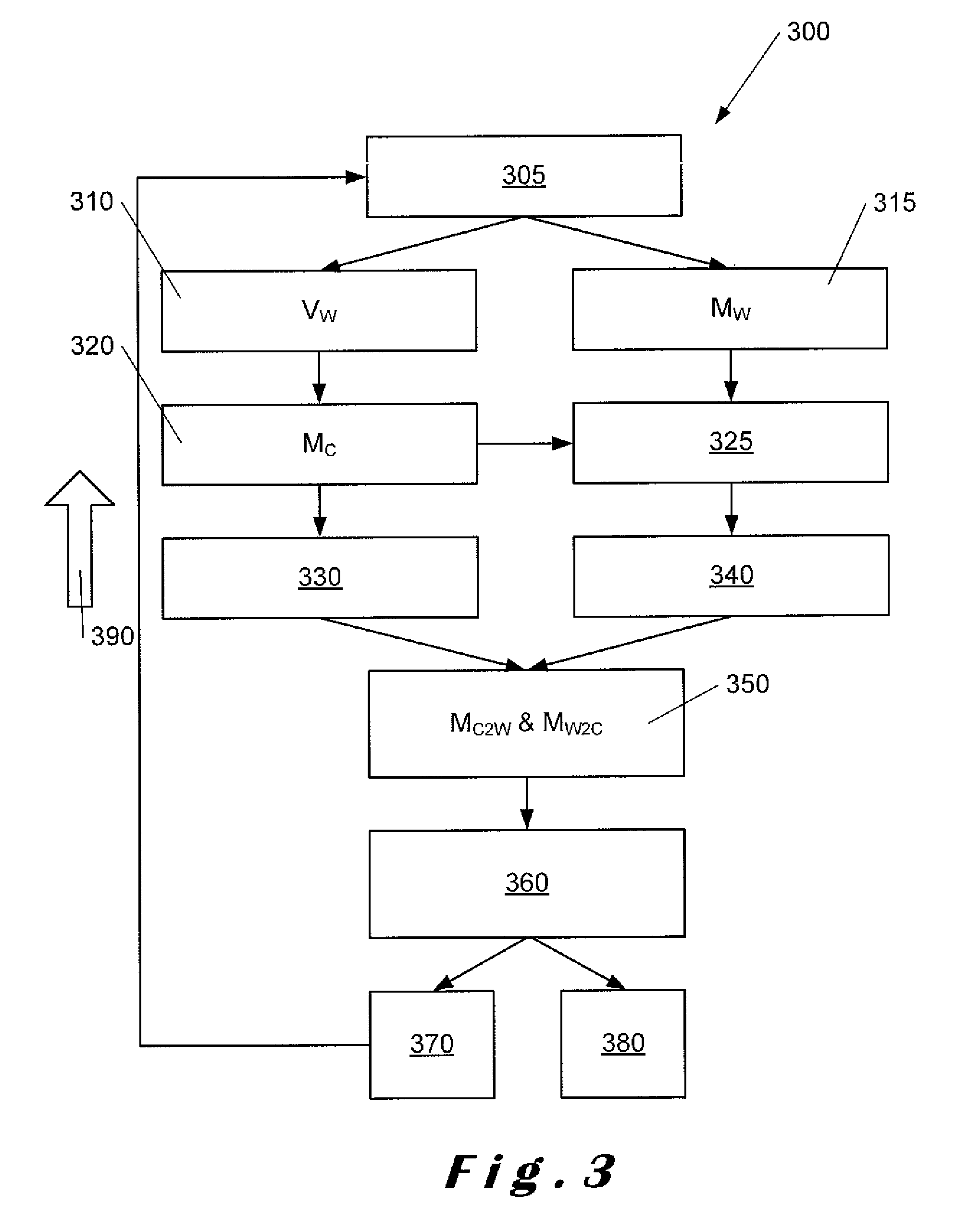
[0025]It is another object of the invention to provide a method for determining a transformation that allows for the application of forward and reverse data measurement expressed in the camera or virtual coordinate system into data expressed in the world or real coordinate system.
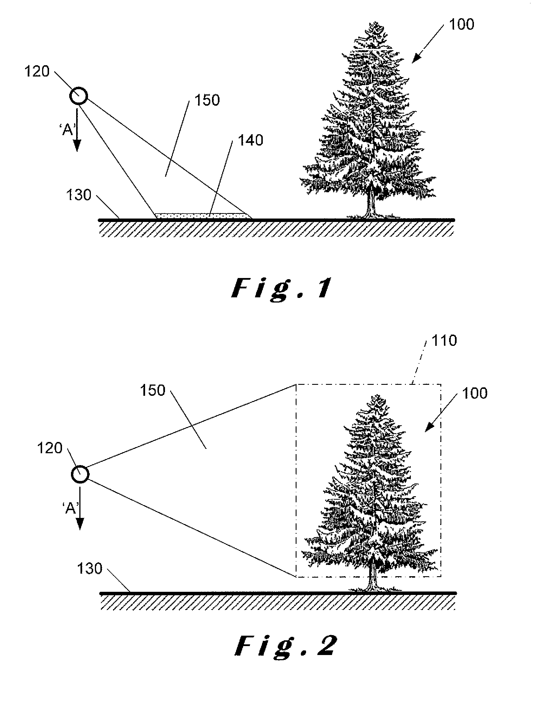
[0027]It is yet another object of the present invention to provide a method of circumventing low visibility of the ground in a scene.
[0028]It is a yet further object of the invention to provide a system for improving and automating the calibration process between a camera coordinate system and the real world coordinate system by iteratively adjusting the camera so that at least one axis of the camera coordinate system is aligned with a plane defined by the real world coordinate system.

Problems solved by technology

One common problem which occurs during such analysis is the unknown orientation of the camera.
Furthermore, calibration is most often performed off-line, and not in real-time, on a static camera.
In addition, these methods tend not to correct for all possible orientations of the 3D camera, and, they are often limited to being used with cameras in specific orientations, for example, generally downwardly- or generally horizontally-oriented cameras.

Method used

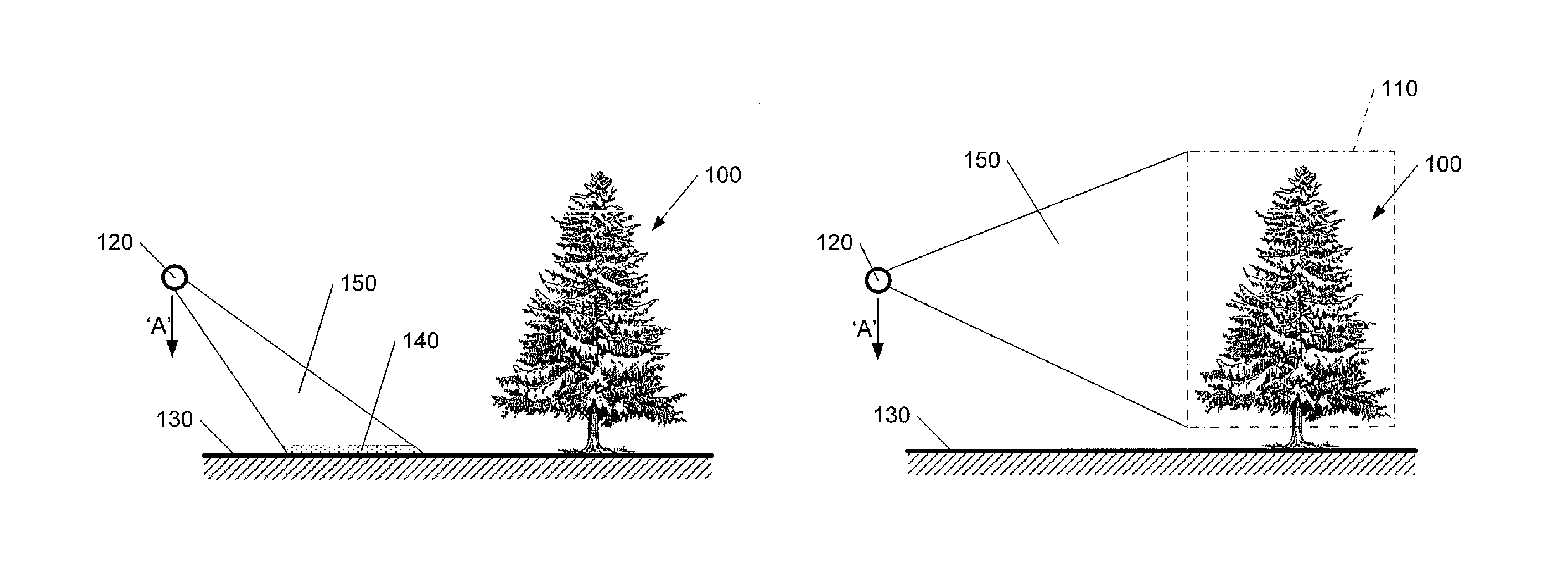

Image

  • Automatic scene calibration
  • Automatic scene calibration
  • Automatic scene calibration

Examples


Embodiment Construction

[0068]The present invention will be described with respect to particular embodiments and with reference to certain drawings but the invention is not limited thereto. The drawings described are only schematic and are non-limiting. In the drawings, the size of some of the elements may be exaggerated and not drawn on scale for illustrative purposes.

[0069]It will be understood that the terms “vertical” and “horizontal” are used herein refer to particular orientations of the Figures and these terms are not limitations to the specific embodiments described herein.

[0070]The present invention relates to a method and a system for geometric calibration of machine vision. It more particularly concerns the calibration of a three-dimensional (3D) camera, and includes static and dynamic detection modes of the extrinsic camera parameters in order to improve the management and analysis of a captured scene. Such calibration includes the determination of a camera rotation and translation from the rea...


PUM


Abstract

Described herein is a method of calibrating a three-dimensional imaging system. During calibration, a position and an orientation of the three-dimensional imaging system is determined with respect to a first parameter comprising a real world vertical direction (Vw) and to a second parameter comprising an origin of a three-dimensional scene captured by the imaging system. The first and second parameters are used to derive a calibration matrix (MC2w) which is used to convert measurements from a virtual coordinate system (Mc) of the three-dimensional imaging system into a real coordinate system (Mw) related to the real world. The calibration matrix (MC2w) is used to rectify measurements prior to signal processing. An inverse calibration matrix (Mw2c) is also determined. Continuous monitoring and adjustment of the setup of the three-dimensional imaging system is carried out and the calibration matrix (Mc2w) and its inverse (Mw2c) are adjusted accordingly.

Description

FIELD OF THE INVENTION[0001]The present invention relates to camera calibration and is more particularly concerned with automatically calibrating the position and orientation of a Three-dimensional (3D) sensing camera with respect to the real world.BACKGROUND TO THE INVENTION[0002]Three-dimensional (3D) or depth sensing cameras, namely, structured light 3D cameras, time-of-flight 3D cameras, and stereo-vision 3D cameras, are imaging devices that acquire depth images. A depth image represents distances from the scene to the 3D. 3D camera devices, and the depth images they provide, are used to analyse static and dynamic 3D elements within a captured scene, such as, objects and users.[0003]Analysis of a captured scene may include detection, localisation, and identification of objects and / or users and their respective analysis. One common problem which occurs during such analysis is the unknown orientation of the camera. For example, a vertically-oriented object in the scene may appear ...

Claims


Application Information

Patent Timeline
Patent Type & Authority Patents(United States)
IPC IPC(8): H04N13/02G06T7/00
CPCH04N13/0246G06T7/85G06T7/50G06T7/80G06T2207/30244H04N13/246G06T1/00G06T3/00G06T7/00H04N13/00
Inventor BAELE, XAVIERMARTINEZ GONZALEZ, JAVIER
Owner SOFTKINETIC SOFTWARE
Learn More