
System for recovering waste heat

a waste heat and recovery system technology, applied in the direction of sustainable manufacturing/processing, separation processes, furnaces, etc., can solve the problems of high investment and operation costs, inability to safely operate the column, and waste heat at relatively low temperatures being discharged to the environment. , to achieve the effect of improving the energy efficiency of the column

Active Publication Date: 2017-02-21
SK PICGLOBAL CO LTD
View PDF38 Cites 1 Cited by
  • Summary
  • Abstract
  • Description
  • Claims
  • Application Information

AI Technical Summary

Benefits of technology

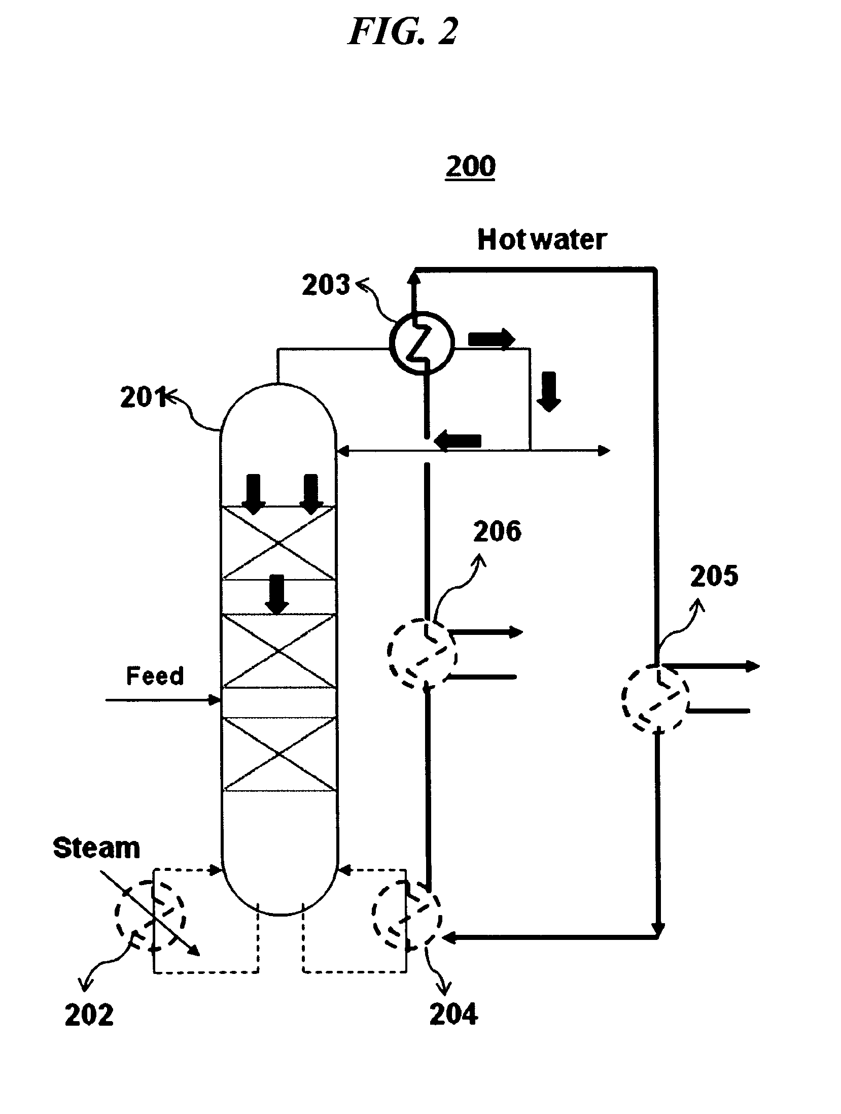
[0010]Therefore, it is an object of the present invention to provide a system for recovering waste heat generated in the upper part of a column and for recycling the recovered heat to the column, to thereby improve the energy efficiency thereof.

Problems solved by technology

On the other hand, waste heat at relatively low temperatures is merely discharged to the environment due to technical difficulties as well as high equipment costs for its recovery.
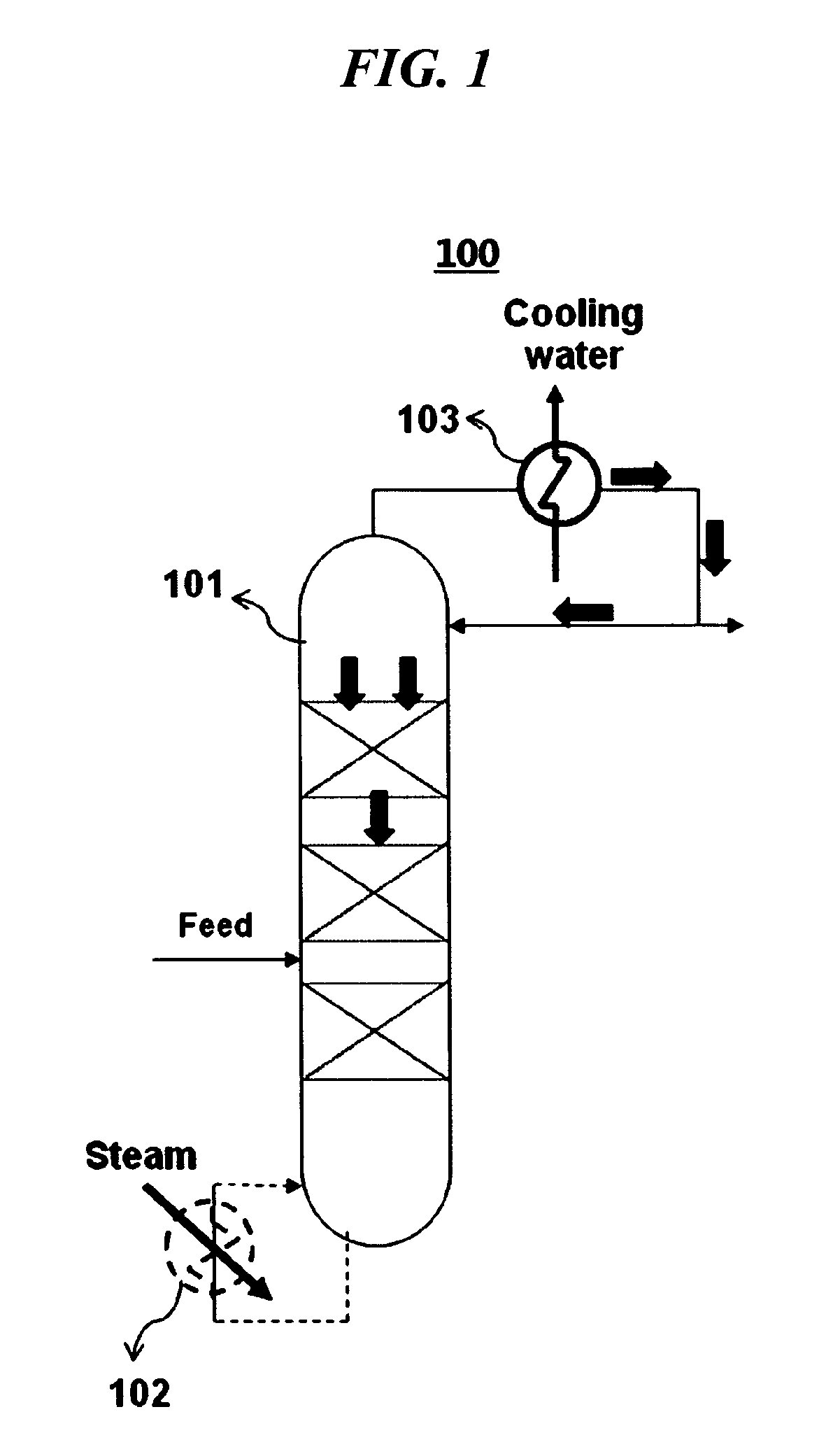
However, an MVR requires high investments and operation costs.
Further, the column may not be safely operated in case the MVR system fails since no cooling source is then available.
However, it requires a large amount of high pressure vapor for producing usable steam, which may result in a loss of secondary steam due to the disruption of the overall steam balance.

Method used


Image

  • System for recovering waste heat
  • System for recovering waste heat
  • System for recovering waste heat

Examples


example

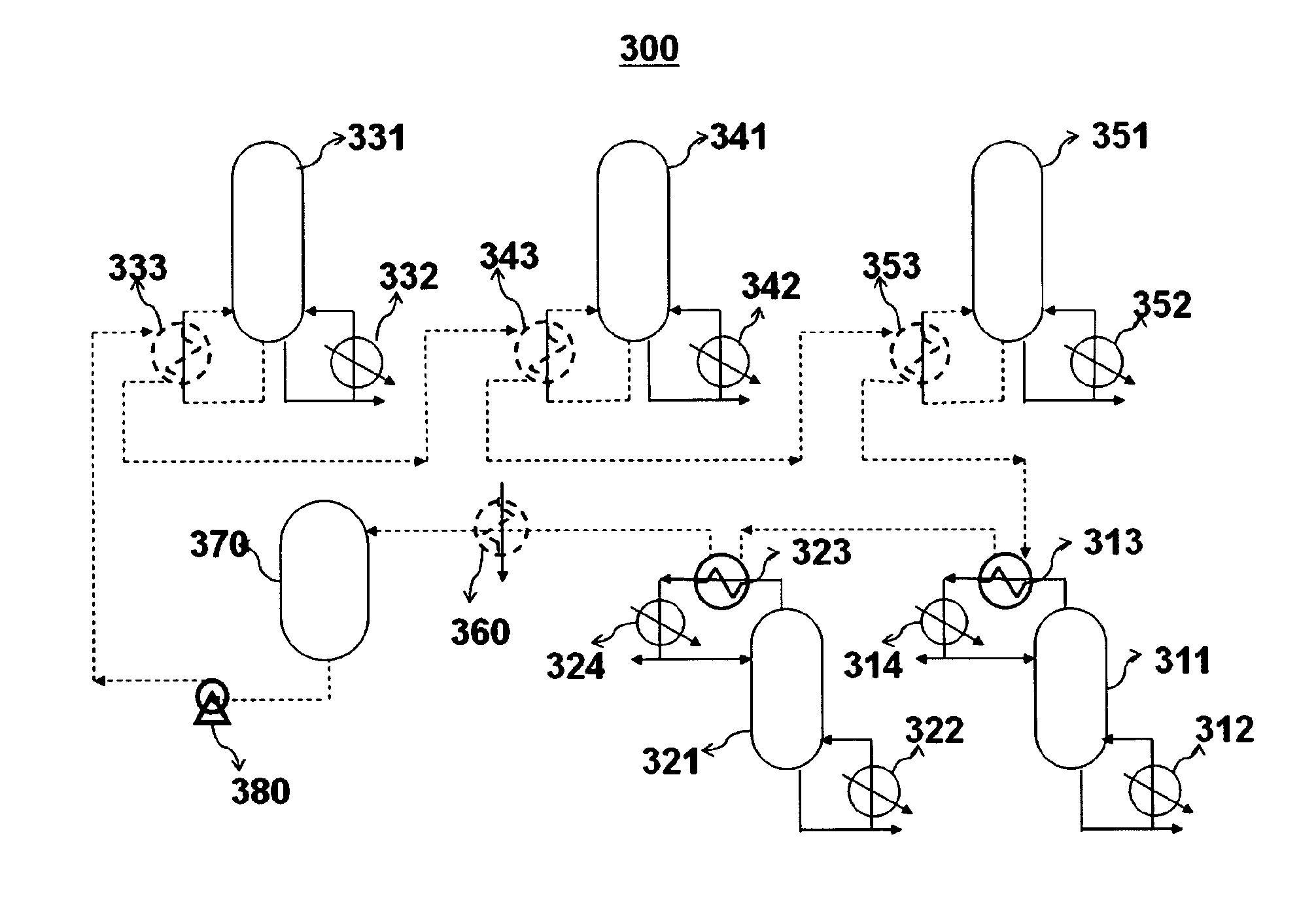
[0076]The waste heat recovery system as illustrated in FIG. 5 was employed for recovering waste heat.

[0077]To be specific, waste heat generated from a column 531, an incinerator 532, a cooler 533, and a column 534 was recovered and supplied to a hot water generator 530 to produce hot water, which was stored in a storage device 540. The temperature of hot water sampled from the storage device 540 was 116° C. The hot water at 116° C. supplied heat to a hot water reboiler 513 of a first column 511 (operating temperature: 77° C.) via a hot water feeder 550 at a flow rate of 150 t / h. The flow rate and the temperature of the hot water fed to the hot water reboiler 513 were controlled by a controller 560. The temperature of the hot water discharged from the hot water reboiler 513, after it had transferred heat to the first column 511, was 89° C. The hot water then supplied heat to a second column 521 (operating temperature: 58° C.) by preheating the feed to the second column 521 by a hot w...


PUM


Abstract

Provided is a system for recovering waste heat discharged from distillation columns, incinerators, blast columns, smelting columns, and the like at relatively low temperatures to produce hot water in high efficiency, which can be used in various industrial fields. The investment and operating costs of the waste heat recovery system are relatively low as compared with the conventional systems.

Description

CROSS REFERENCE TO RELATED APPLICATIONS[0001]This application is a National Stage of International Application No. PCT / KR2010 / 008521 filed Nov. 30, 2010, claiming priority based on Korean Patent Application No. 10-2009-0123498, filed Dec. 11, 2009, the contents of all of which are incorporated herein by reference in their entirety.FIELD OF THE INVENTION[0002]The present invention relates to a system for recovering waste heat generated by such furnaces as distillation columns, incinerators, blast columns, and smelting columns used in various industrial fields.BACKGROUND OF THE INVENTION[0003]Waste heat refers to heat generated by such furnaces as distillation columns, incinerators, blast columns, and smelting columns used in various industrial fields for which no useful application is found. Waste heat produced by furnaces, boilers, dry facilities, and air conditioning facilities is often discharged in the form of combustion flue gas, whereas waste heat produced during heating, disti...

Claims


Application Information

Patent Timeline
Patent Type & Authority Patents(United States)
IPC IPC(8): F28D15/00B01D1/28B01D1/00F27D17/00F01K23/06B01D3/00F01K17/02F01K17/06F28D21/00
CPCF28D15/00B01D1/0058B01D1/2856B01D3/007F01K17/02F01K17/06F01K23/064F27D17/004C21B2100/06C21C2100/06F28D21/0003Y02P70/34Y02P70/10F28D7/00
Inventor YANG, HOJINWON, KIDONKIM, JUNTAELEE, DOOJINPARK, SOO HYUN
Owner SK PICGLOBAL CO LTD
Learn More