Combustion experimental apparatus
a technology of experimental apparatus and combustion chamber, which is applied in the direction of combustion types, instruments, material flash points, etc., can solve the problems of large measurement errors and achieve the effect of easy carrying out combustion experiments
- Summary
- Abstract
- Description
- Claims
- Application Information
AI Technical Summary
Benefits of technology
Problems solved by technology
Method used
Image
Examples
first embodiment
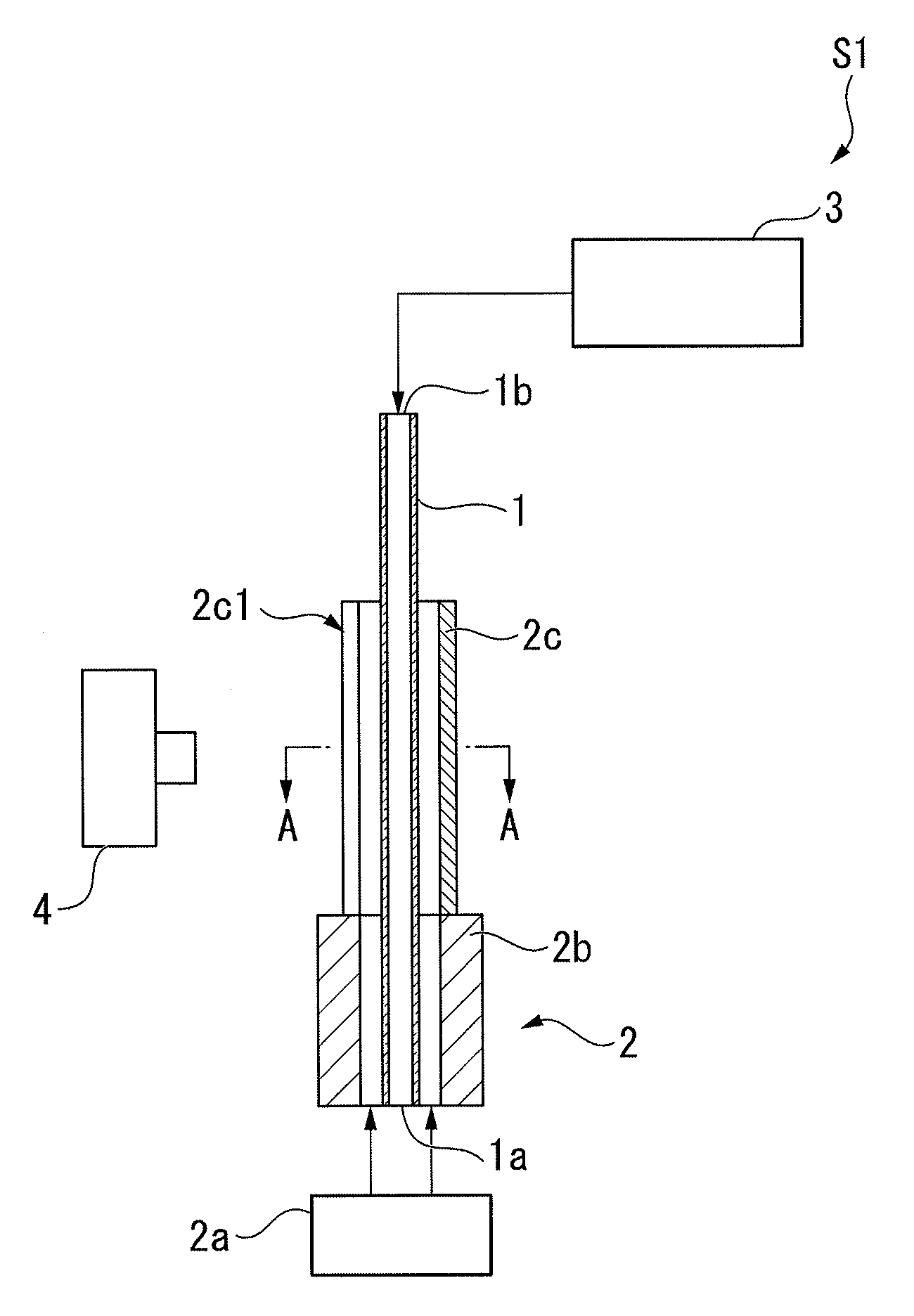
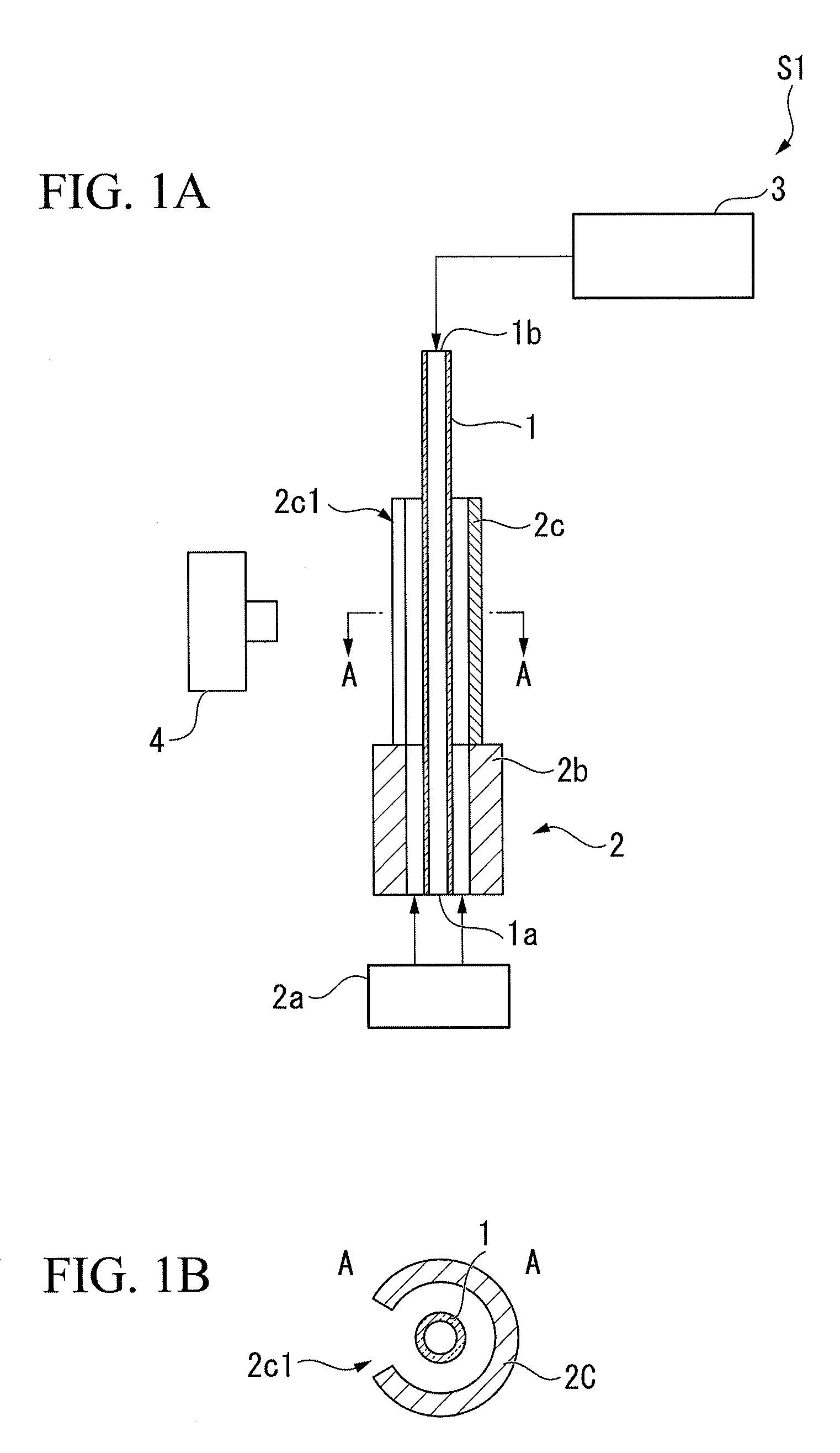
[0030]FIGS. 1A and 1B are schematic views showing the configuration of a combustion experimental apparatus S1 in this embodiment.
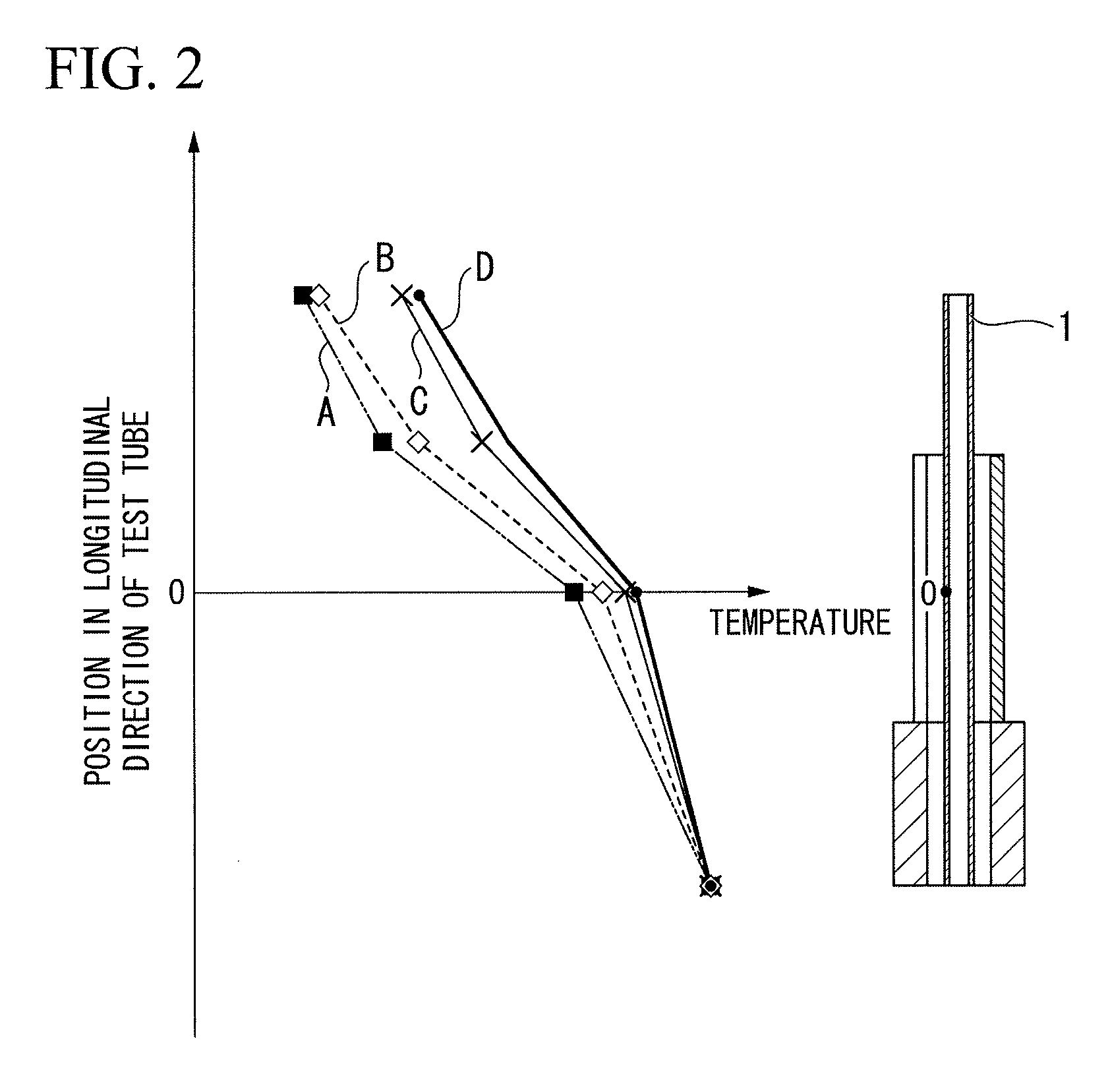
[0031]The combustion experimental apparatus S1 in this embodiment is an apparatus to combust test evaluation gas containing fuel, thereby forming flames, and to obtain the positions of the flames, when measuring the ignition temperature of the fuel.
[0032]As shown in FIG. 1A, the combustion experimental apparatus S1 in this embodiment includes a test tube 1, a temperature-adjusting gas supply portion 2 (temperature-adjusting gas supply device), a test evaluation gas supply portion 3 (supply device), and a camera 4 (flame position-obtaining device).
[0033]The test tube 1 is a tube in which flames are formed, and in which the internal flow path thereof has a diameter less than a flame-quenching distance in a normal temperature. In order to transfer flames inside the flow path, the flow path has to have a certain cross-sectional area. If the cross-sectional are...
second embodiment
[0078]Next, a second embodiment of the present invention is described below. In addition, in the description of this embodiment, the explanations regarding the same parts as that of the first embodiment are omitted or simplified.
[0079]FIGS. 3A and 3B are schematic views showing the configuration of a combustion experimental apparatus S2 in this embodiment. As shown in these drawings, the combustion experimental apparatus S2 in this embodiment includes a guide part 2d formed of a glass tube (transparent tube) surrounding the test tube 1 and having the transparency for the light emitted from flames, instead of the guide part 2c included in the combustion experimental apparatus S1 in the first embodiment and formed of a cylindrical heat-insulating member.
[0080]According to the combustion experimental apparatus S2 in this embodiment adopting the above configuration, since the guide part 2d has the transparency for the light emitted from flames, an opening does not have to be provided in...
third embodiment
[0082]Next, a third embodiment of the present invention is described below. In addition, in the description of this embodiment, the explanations regarding the same parts as that of the first embodiment are omitted or simplified.
[0083]FIGS. 4A and 4B are schematic views showing the configuration of a combustion experimental apparatus S3 in this embodiment. As shown in these drawings, the combustion experimental apparatus S3 in this embodiment includes a guide part 2e formed of a heat-insulating member and having openings 2e1 each provided in the side of the camera 4 and in the side opposite to the camera 4, instead of the guide part 2c included in the combustion experimental apparatus S1 in the first embodiment and formed of a cylindrical heat-insulating member.
[0084]According to the combustion experimental apparatus S3 in this embodiment having the above configuration, the positions of flames can be reliably obtained through the opening 2e1 of the guide part 2e provided in the side ...
PUM
| Property | Measurement | Unit |
|---|---|---|
| pressure | aaaaa | aaaaa |
| diameter | aaaaa | aaaaa |
| temperature | aaaaa | aaaaa |
Abstract
Description
Claims
Application Information
 - R&D
- Intellectual Property
- Life Sciences
- Materials
- Tech Scout
- Unparalleled Data Quality
- Higher Quality Content
- 60% Fewer Hallucinations
Browse by: Latest US Patents, China's latest patents, Technical Efficacy Thesaurus, Application Domain, Technology Topic, Popular Technical Reports.
© 2025 PatSnap. All rights reserved.Legal|Privacy policy|Modern Slavery Act Transparency Statement|Sitemap|About US| Contact US: help@patsnap.com


