
Lighted arrow nock

a technology of lighted arrows and nocks, which is applied in the field of lighted arrow nocks, can solve the problems of complicated structure of turning on or off the light, and achieve the effects of simple configuration, convenient use and easy operation

Inactive Publication Date: 2017-01-17
KIM JAE WOO
View PDF6 Cites 25 Cited by
  • Summary
  • Abstract
  • Description
  • Claims
  • Application Information

AI Technical Summary

Benefits of technology

The present invention is a lighted arrow nock that can be easily turned on or off, and connected to an arrow. It includes an arrow adaptor with a battery insertion hole and an operator engaging hole, and a light operator with a light insertion groove and an adaptor insertion portion. The light operator can be guided towards the operator engaging hole by a guide rail, and its movement is restricted to ON and OFF positions by a position restricting portion. The lighted arrow nock has the advantage of easy use and the nock is firmly engaged to the arrow shaft, so the light is easily operated. The battery is provided integrally with the light, so the configuration is simple and additional wiring is not necessary.

Problems solved by technology

The lighted arrow of the related art has problems in that the structure of turning on or off the light is complicated, and a device sensitive to on / off operation should be employed.

Method used


Image

  • Lighted arrow nock
  • Lighted arrow nock
  • Lighted arrow nock

Examples


first embodiment

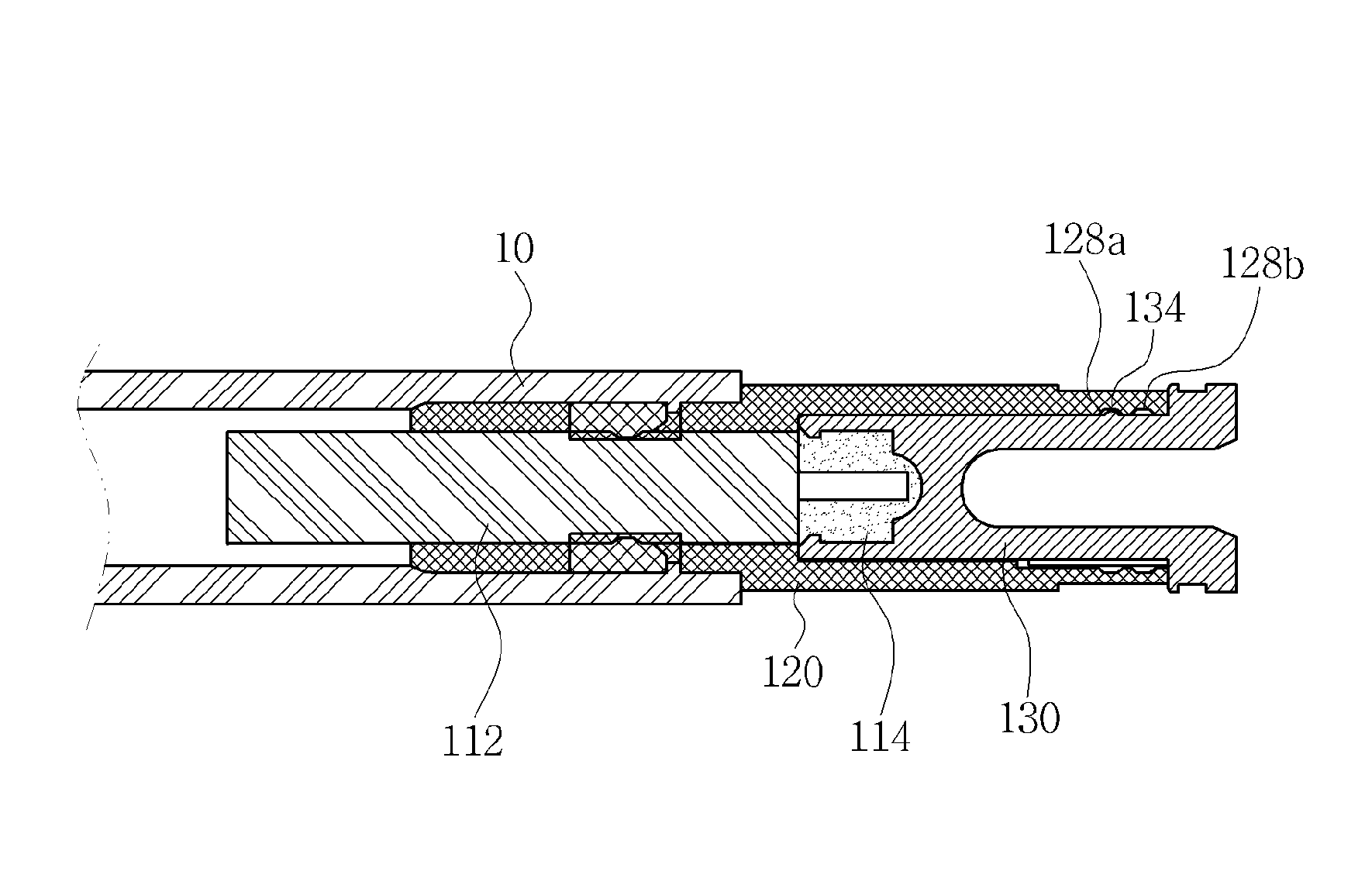
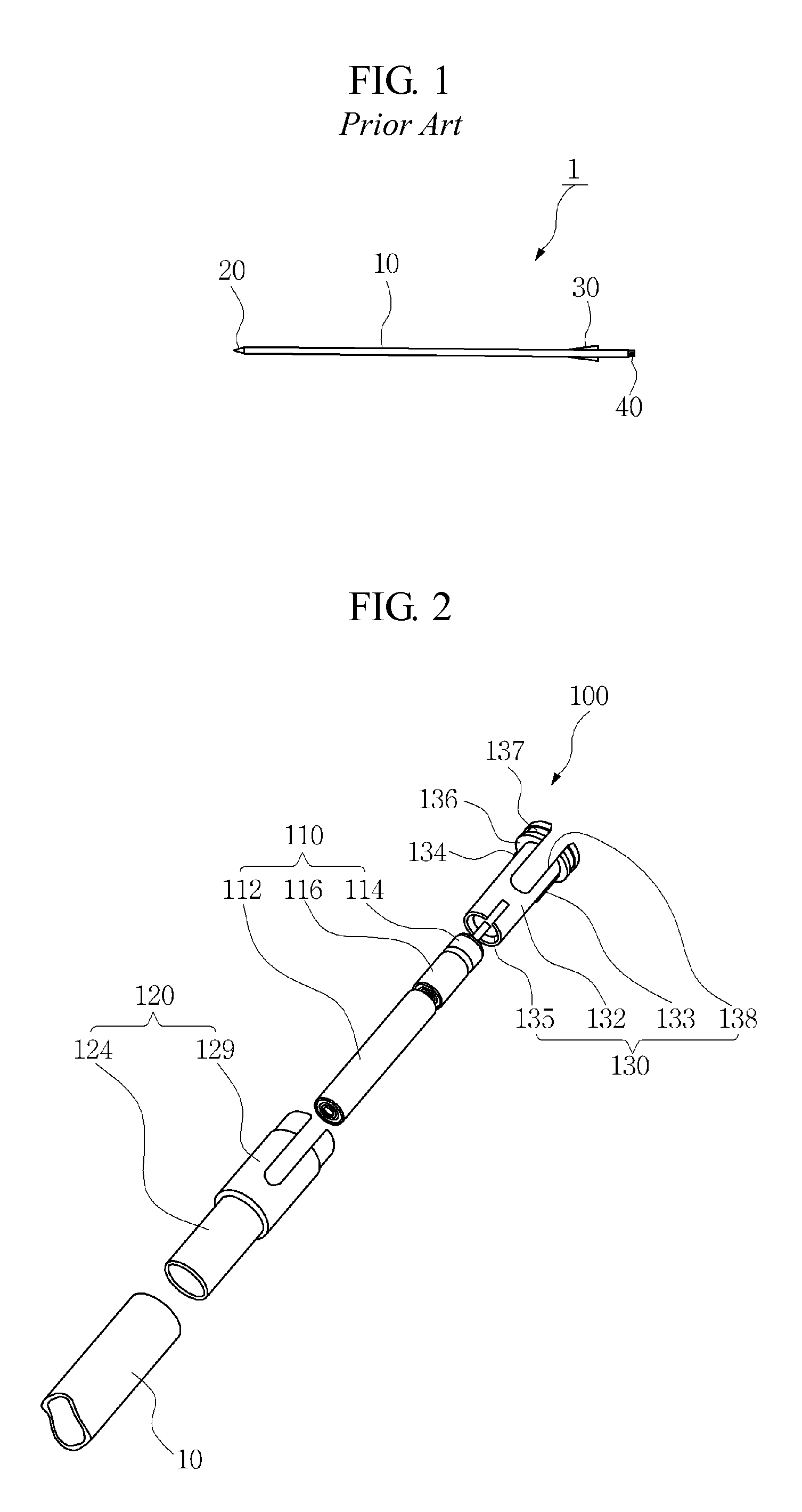
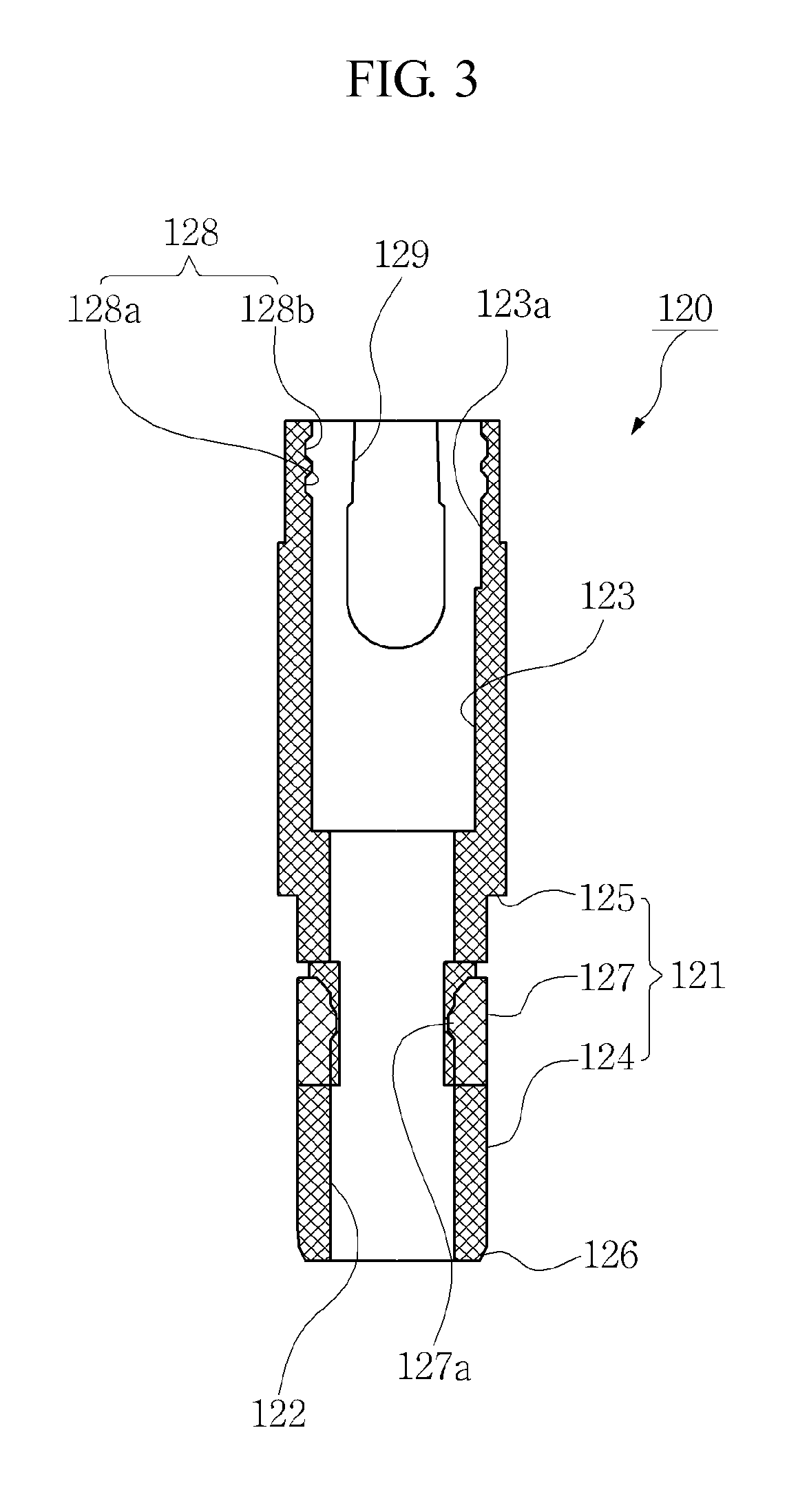
[0036]A lighted arrow nock 100 according to the embodiment includes, as illustrated in FIG. 2, a light emitting unit 110, an arrow adaptor 120, and a light operator 130.

[0037]First, the light emitting unit 110 has a battery provided integrally with a light. Specifically, the light emitting unit 110 may have, as illustrated in FIGS. 2 and 5, a battery 112 positioned at a lower portion and a light 114 positioned at an upper portion. The battery 112 positioned at the lower portion is formed in a cylindrical shape, and the light 114 is connected to an upper portion of the battery 112. As the light 114 is pushed toward the battery 112, the light 114 is turned on. As the light 114 is pulled away from the battery 112, the light is turned off.

[0038]As illustrated in FIGS. 2 and 5, a middle portion of the battery 112 is preferably provided with a protrusion insertion groove 116 to receive a protrusion 127a of the arrow adaptor 120, as described below, and the protrusion insertion groove 116 ...

second embodiment

[0064]A lighted arrow nock 200 according to this embodiment includes a light emitting unit 210, an arrow adaptor 220, and a light operator 230, similar to the first embodiment.

[0065]The light emitting unit 210 has a light 212 and a battery 214 which is separated from the light 212, as illustrated in FIG. 8. Specifically, the battery 214 is formed in a cylinder shape, and has a terminal 215 protruding upwardly from an upper portion thereof. An outer peripheral surface of the cylindrical battery 214 serves as another terminal having polarity different from the terminal 215.

[0066]As illustrated in FIG. 8, the light 212 is separated from the battery 214, and has first and second contact terminals 211 and 213. Herein, the first contact terminal 211 is provided to be brought into contact with the outer peripheral surface of the cylindrical battery 214, as illustrated in FIG. 9, while the second contact terminal 213 is moved to be brought into contact with the terminal 215 or to be away fr...


PUM


Abstract

A lighted arrow nock capable of easily turning on or off a light, and being easily connected to an arrow shaft includes a light emitting unit including a light and a battery and turning on or off the light by moving the light toward the battery or away from the battery; an arrow adaptor which includes a cylindrical structure so that an outer surface is inserted into a rear end of an arrow, in which the battery is inserted into an inner space of the arrow adaptor; and a light operator which is inserted in an upper portion of the arrow adaptor, while a lower portion of the light operator receives the light, and is moved up and down to turn on or off the light in a state in which the light operator is inserted in the arrow adaptor.

Description

BACKGROUND OF THE INVENTION[0001]Field of the Invention[0002]The present invention relates to an arrow nock, and, more specifically, to a lighted arrow nock capable of easily turning on or off a light, and being easily connected to an arrow shaft.[0003]Background of the Related Art[0004]In general, an arrow 1 used for archery includes, as illustrated in FIG. 1, an arrow shaft 10 of a cylindrical cross section made of duralumin, glass fiber, carbon fiber, or the like to form a body, an arrowhead 20 fitted to a front end of the arrow shaft 10, feathers 30 designed to stabilize flight of the arrow 1 and to keep the arrow pointed in the direction of travel, and a nock 40 which is a notch in the rearmost end of the arrow and serves the arrow in place on the string as a bow is being drawn.[0005]There has been recently developed a technology of providing the arrow with a lighting function in order to enable a user to effectively enjoy the archery even at night or on a cloudy day. In this i...

Claims


Application Information

Patent Timeline
Patent Type & Authority Patents(United States)
IPC IPC(8): F42B6/06F42B12/38
CPCF42B6/06F42B12/382
Inventor KIM, JAE WOO
Owner KIM JAE WOO
Learn More