
Systems and methods for mapping the ocular surface

a technology of ocular surface and mapping method, which is applied in the field of three-dimensional imaging, can solve the problems of lack of data on the corneal periphery, lack of corneal periphery and sclera coverage needed for scleral lens fitting, and inability to measure scleral topography with placido disks

Active Publication Date: 2017-01-17
PRECISION OCULAR METROLOGY LLC
View PDF15 Cites 7 Cited by
  • Summary
  • Abstract
  • Description
  • Claims
  • Application Information

AI Technical Summary

Benefits of technology

The patent describes a method for measuring the surface of the eye using a special dye coating and a projector that projects light in a way that triggers the dye to emit fluorescent light. The eye's surface is then detected using a camera. The method is useful for accurate and precise measurements of the cornea and sclera, even when the eyelids are closed. The method combines multiple measurements taken from different angles to create a complete and registered model of the eye's surface. Overall, the method helps to get a better understanding of the structure and variations of the eye's surface, which can aid in the diagnosis and treatment of various ophthalmic conditions.

Problems solved by technology

But in most cases the data on the central zone needs to be interpolated and the data on the corneal periphery is often missing due to limited reflection.
Additionally, Placido disks are not capable of measuring the scleral topography, which is important for custom fitting of scleral lenses.
While these systems provide better measurement of the corneal apex they lack the coverage of the corneal periphery and sclera needed for scleral lens fitting.

Method used


Image

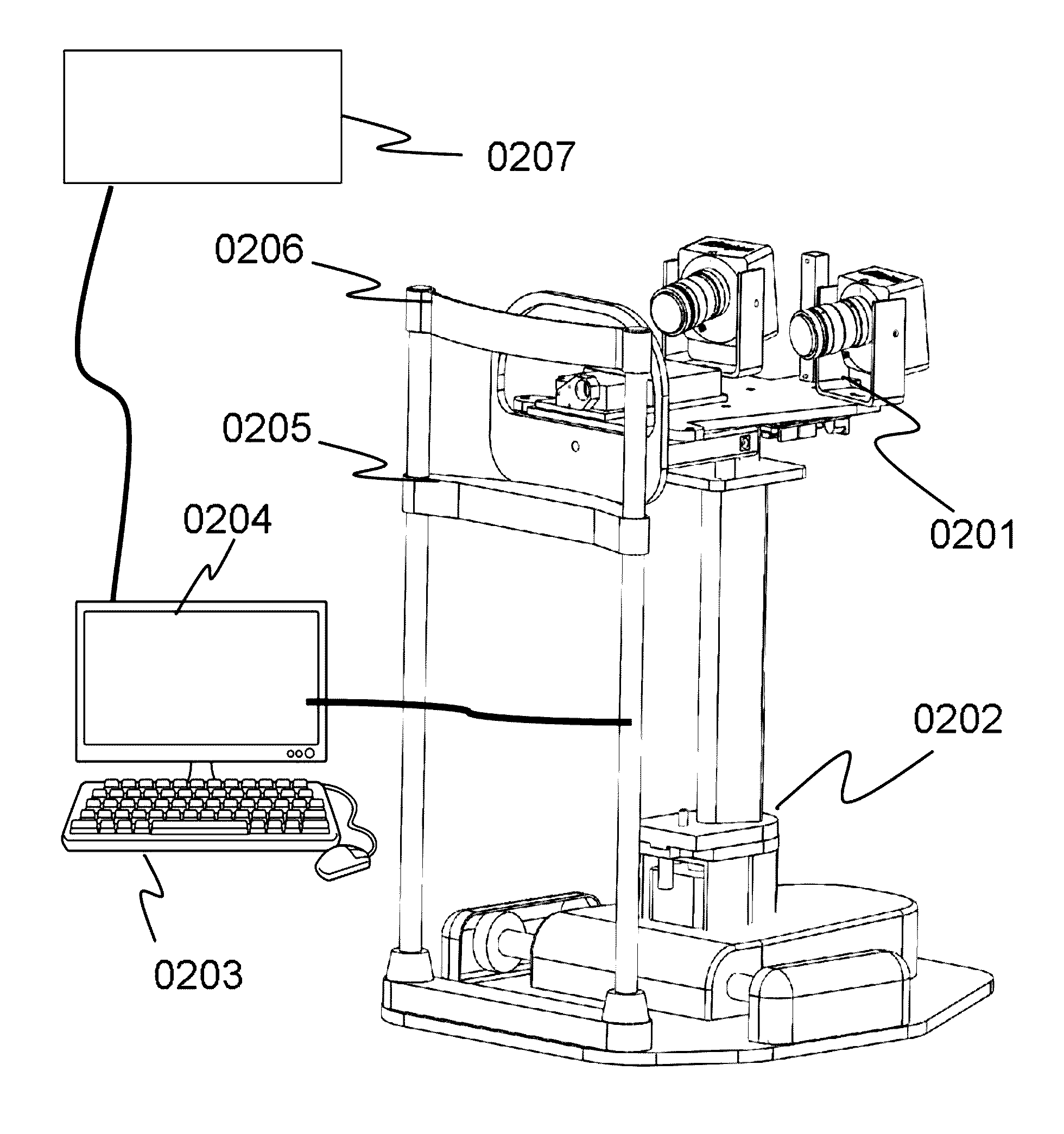
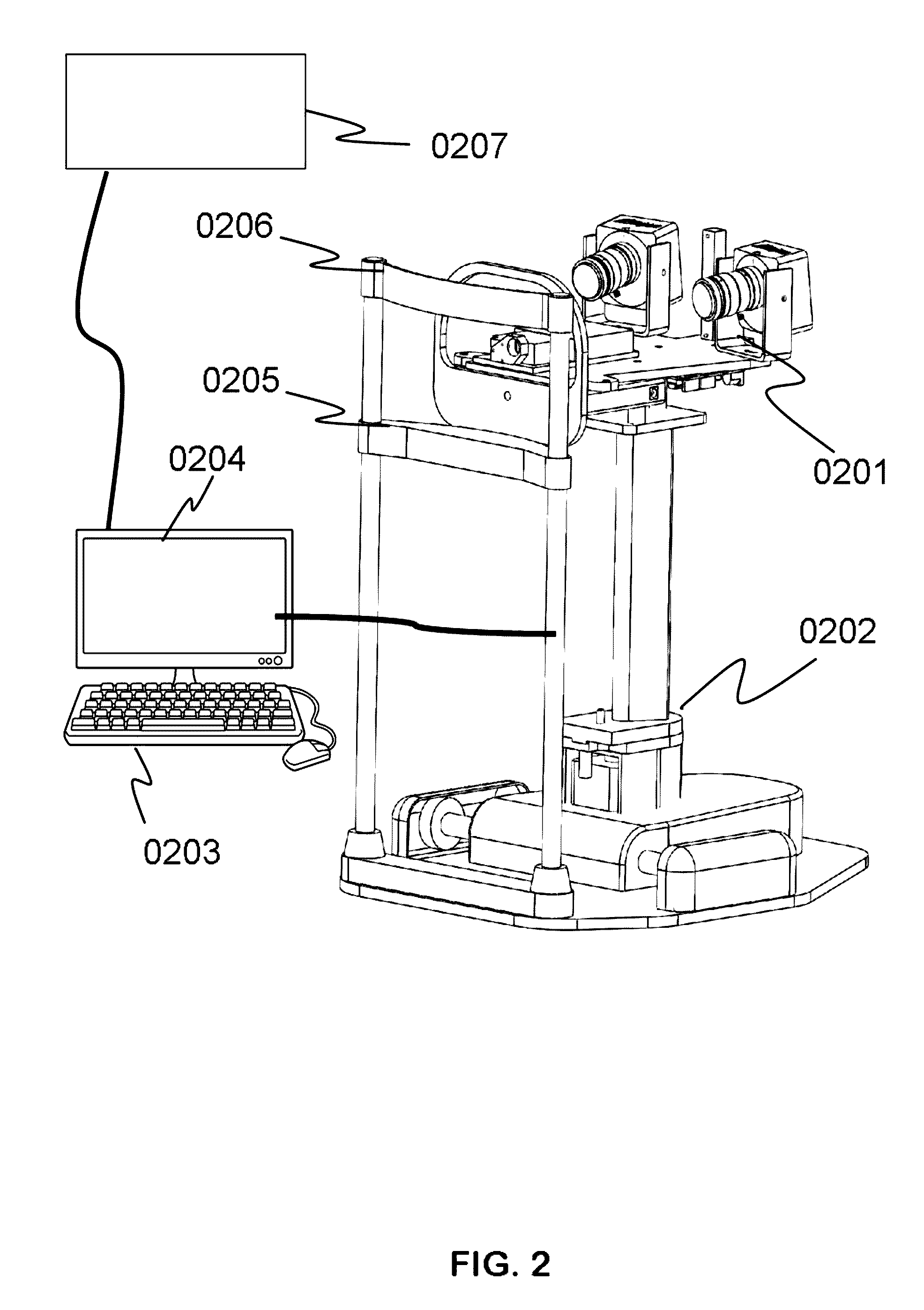
  • Systems and methods for mapping the ocular surface
  • Systems and methods for mapping the ocular surface
  • Systems and methods for mapping the ocular surface

Examples


embodiments

Additional Examples and Embodiments

[0091]In various embodiments, the systems and methods disclosed herein may achieve one, some, or all of the following advantages and / or provide some or all of the following functionality.

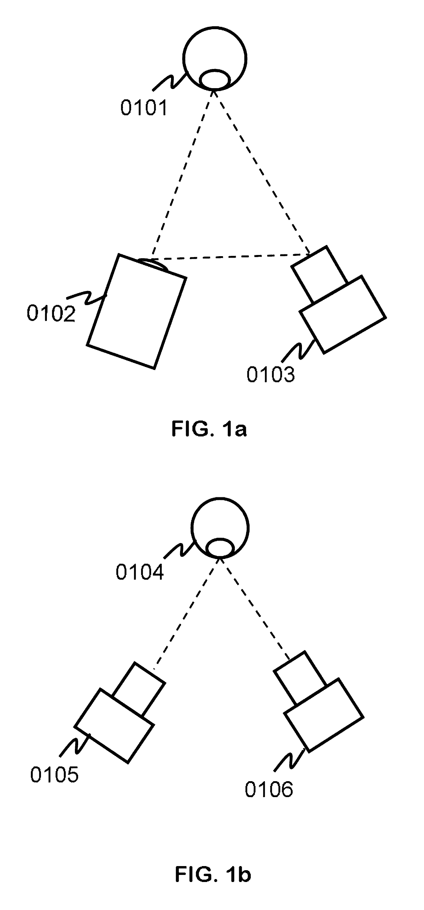
[0092]In some embodiments, three simultaneous independent measurements are used, which may advantageously provide error reduction in overlap regions through averaging, error reduction in overlap regions through constraints, wider field-of-view by having cameras out at angles to the surface to be measure, and / or more accurate tracking, because it may be difficult to use corneal points for tracking.

[0093]In some embodiments, coded structured light is used to map the surface of the object (e.g., the anterior surface of the eye). Pattern sequences can offer higher spatial resolution than single patterns, and unique pixel encoding can eliminate iterative point searching, which advantageously can increase speed and / or accuracy of the mapping.

[0094]In some implementations...


PUM


Abstract

Examples of methods and apparatus for an accurate measurement of the anterior surface of the eye including the corneal and scleral regions are disclosed. The measurements provide a three-dimensional map of the surface which can be used for a variety of ophthalmic and optometric applications from astigmatism and keratoconus diagnostics to scleral lens fitting.

Description

CROSS-REFERENCE TO RELATED APPLICATIONS[0001]This application claims the benefit of and priority to U.S. Provisional Patent Application No. 61 / 962,449, filed Nov. 8, 2013, entitled “SCLERAL TOPOGRAPHY MEASUREMENT DEVICE,” which is hereby incorporated by reference herein in its entirety.BACKGROUND[0002]Technical Field[0003]The present disclosure relates to three dimensional imaging using the structured light approach, and more particularly to ocular surface measurement over the anterior surfaces of the cornea and sclera.[0004]Description of Related Art[0005]The accurate knowledge of the corneal surface is very important for diagnostics and treatment of a number of ocular conditions. Cornea is responsible for about 70% of the refractive power of the eye and therefore the corneal topography has a great importance in determining the quality of vision. It is commonly used for diagnosis of keratoconus, for selecting appropriate soft contact lenses, for fitting scleral lenses, and for topo...

Claims


Application Information

Patent Timeline
Patent Type & Authority Patents(United States)
IPC IPC(8): A61B3/10A61B3/00A61B3/107A61B3/14
CPCA61B3/107A61B3/0025A61B3/0041A61B3/0091A61B3/102A61B3/14G02C7/027G02C7/047
Inventor CATANZARITI, SCOTT P.SARVER, EDWIN J.SANDERS, DONALD R.
Owner PRECISION OCULAR METROLOGY LLC
Learn More