
Power transmission structure of power supply unit

Active Publication Date: 2017-01-03
CHYNG HONG ELECTRONICS
View PDF21 Cites 2 Cited by
  • Summary
  • Abstract
  • Description
  • Claims
  • Application Information

AI Technical Summary

Benefits of technology

The present invention provides a power transmission structure of a power supply unit that can decrease the space occupied by the device, reducing the required interior accommodation space of the unit and reducing its volume. The power transmission structure uses metallic plates to connect components of the unit for power transmission. This results in a flattened structure that decreases the space needed for power transmission.

Problems solved by technology

With the power cords to connect the components of the power supply unit, the power cords occupy too much space, so the power supply unit must have a certain volume and interior space.

Method used


Image

  • Power transmission structure of power supply unit
  • Power transmission structure of power supply unit
  • Power transmission structure of power supply unit

Examples


Embodiment Construction

[0013]Embodiments of the present invention will now be described, by way of example only, with reference to the accompanying drawings.

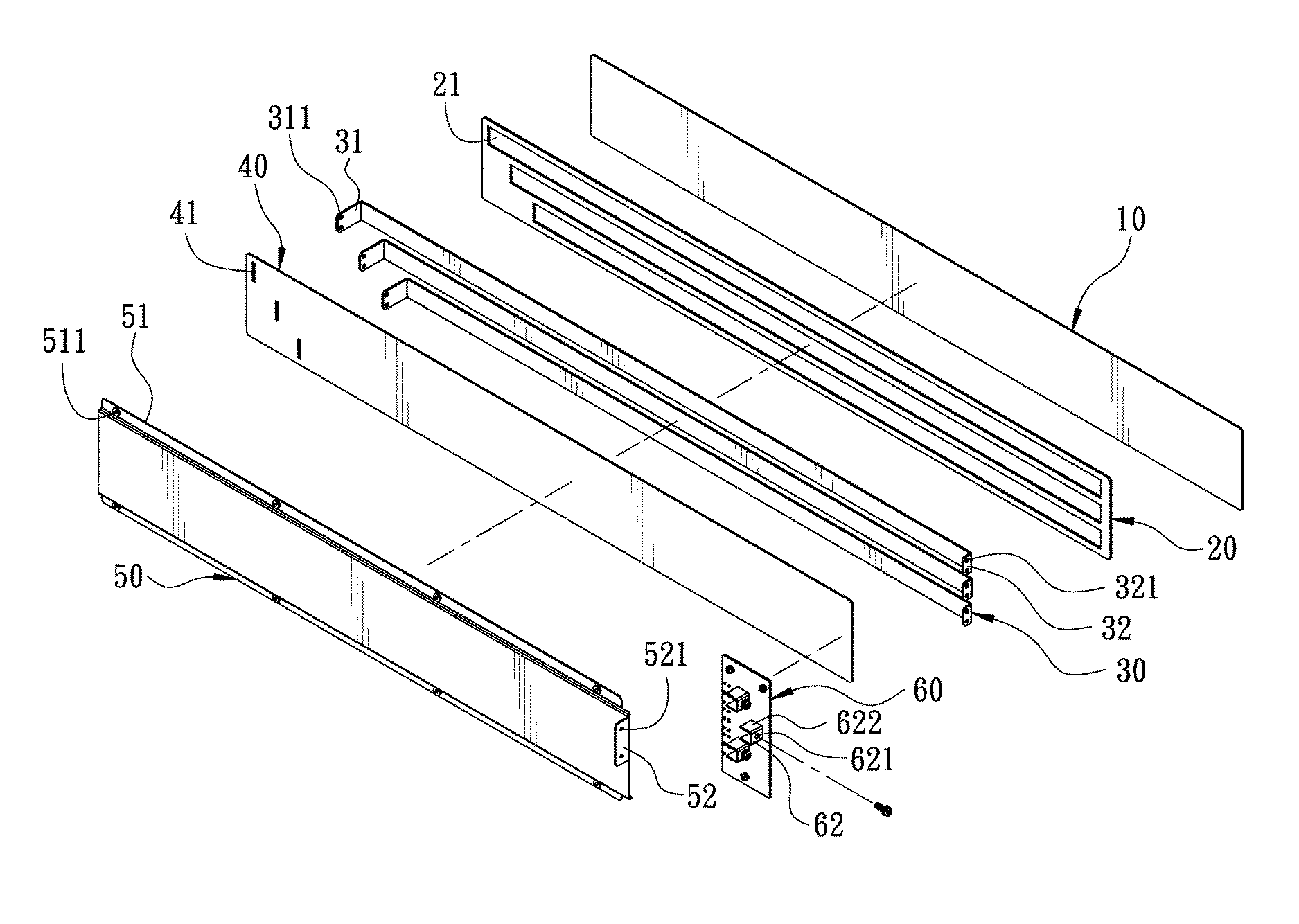
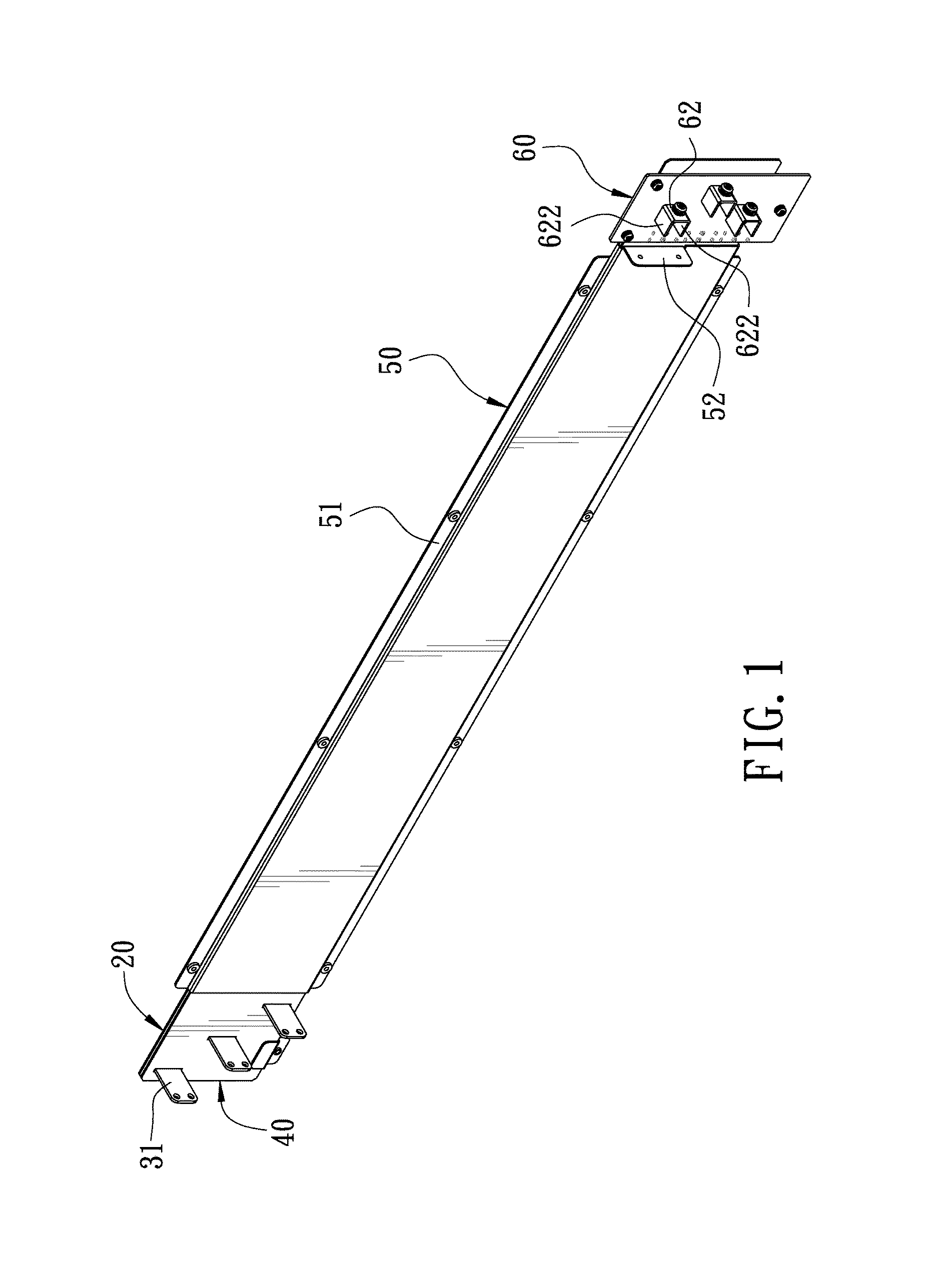
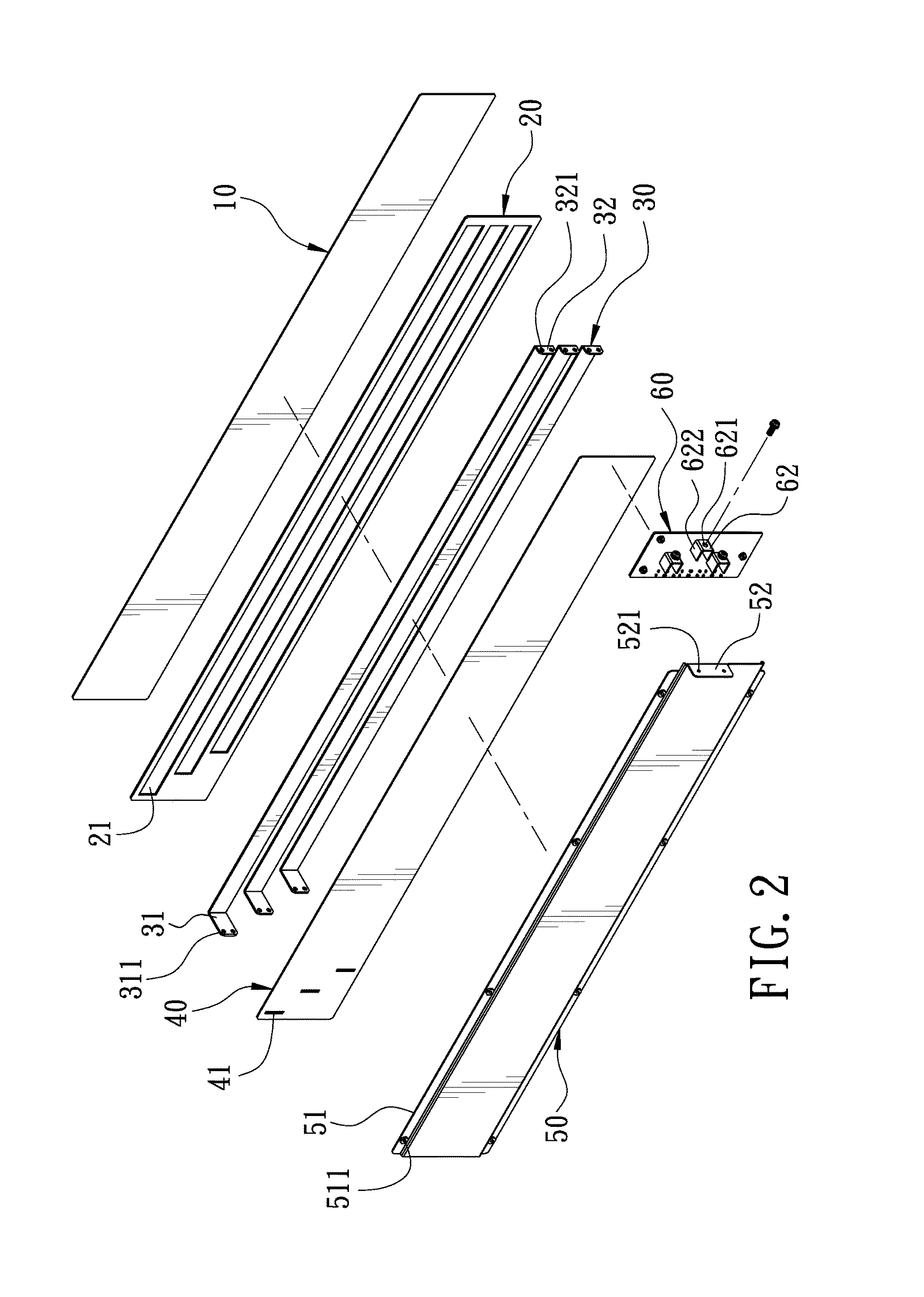
[0014]FIG. 1 is a perspective view of the present invention. FIG. 2 is an exploded view of the present invention. FIG. 3 is a sectional view of the present invention. The present invention discloses a power transmission structure of a power supply unit. FIG. 4 is a schematic view showing the assembly of the present invention. The power supply unit 200 has a case 210. The power transmission structure comprises a base plate 10, a positioning plate 20, a plurality of metallic plates 30, a press plate 40, a fixing plate 50, and a cover plate 60.

[0015]The base plate 10 is an elongate plate. The base plate 10 is made of an insulation material to provide an insulation effect. The base plate 10 is disposed on the inner wall of the case 210.

[0016]The positioning plate 20 is parallel to the base plate 10 and disposed on the base plate 10. The positioning plate ...


PUM


Abstract

A power transmission structure of a power supply unit includes a base plate. The base plate is provided with a plurality of spaced metallic plates. One end of each metallic plate is provided with a first connecting portion and the other end is provided with a second connecting portion to connect the components of the power supply unit respectively for power transmission. Thus, the present invention can take the place of conventional power cords, and the power transmission structure can be flattened to decrease the space occupied by the power transmission device, such that the required interior accommodation space of the power supply unit can be decreased effectively and the volume of the power supply unit can be reduced.

Description

BACKGROUND OF THE INVENTION[0001]1. Field of the Invention[0002]The present invention relates to a power transmission device, and more particularly to a power transmission structure of a power supply unit.[0003]2. Description of the Prior Art[0004]The interior of a conventional power supply unit is provided with a plurality of power cords to connect components and to connect a power input end with a power converting device and to connect the power converting device with a power output end for power transmission. In general, the radial cross-section of a conventional power cord has a circular shape. A conventional power supply unit is provided with power cords having a diameter of at least 8 mm as power transmission. With the power cords to connect the components of the power supply unit, the power cords occupy too much space, so the power supply unit must have a certain volume and interior space. Accordingly, the inventor of the present invention has devoted himself based on his man...

Claims


Application Information

Patent Timeline
IPC IPC(8): H05K7/00H05K7/02
CPCH05K7/02H05K7/1457H05K7/14325H05K7/14329H05K7/1432
Inventor LIN, MU-CHUN
Owner CHYNG HONG ELECTRONICS
Learn More