
Marine navigation light apparatuses and methods of making the same

a technology of light apparatus and marine navigation, which is applied in the direction of point-like light source, light and heating apparatus, transportation and packaging, etc., can solve the problems of dangerous conditions and even fines by waterway authorities, damage or breakage of the pole ligh

Active Publication Date: 2017-01-03
DEVEN RANDAL A +1
View PDF16 Cites 2 Cited by
  • Summary
  • Abstract
  • Description
  • Claims
  • Application Information

AI Technical Summary

Benefits of technology

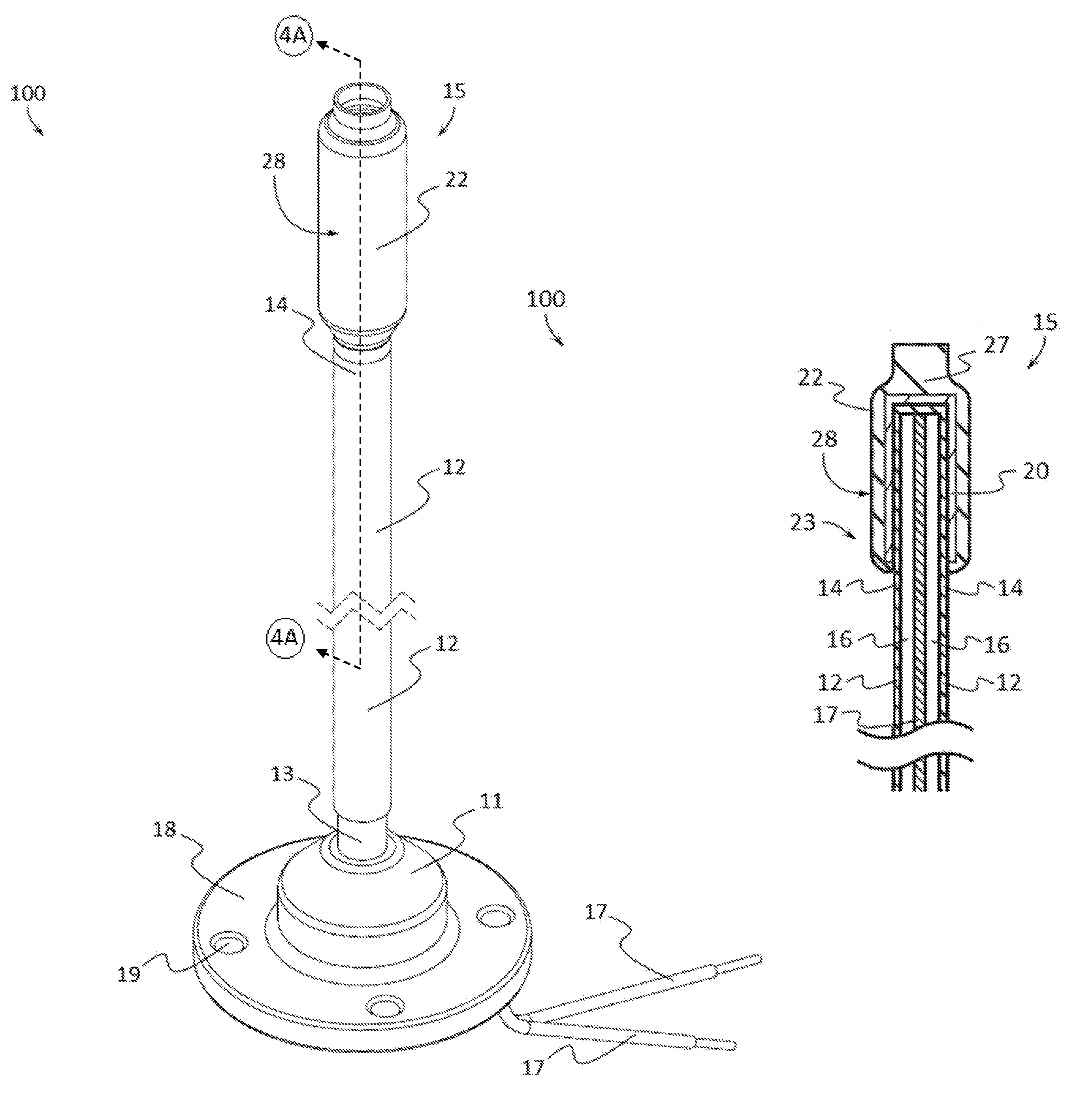
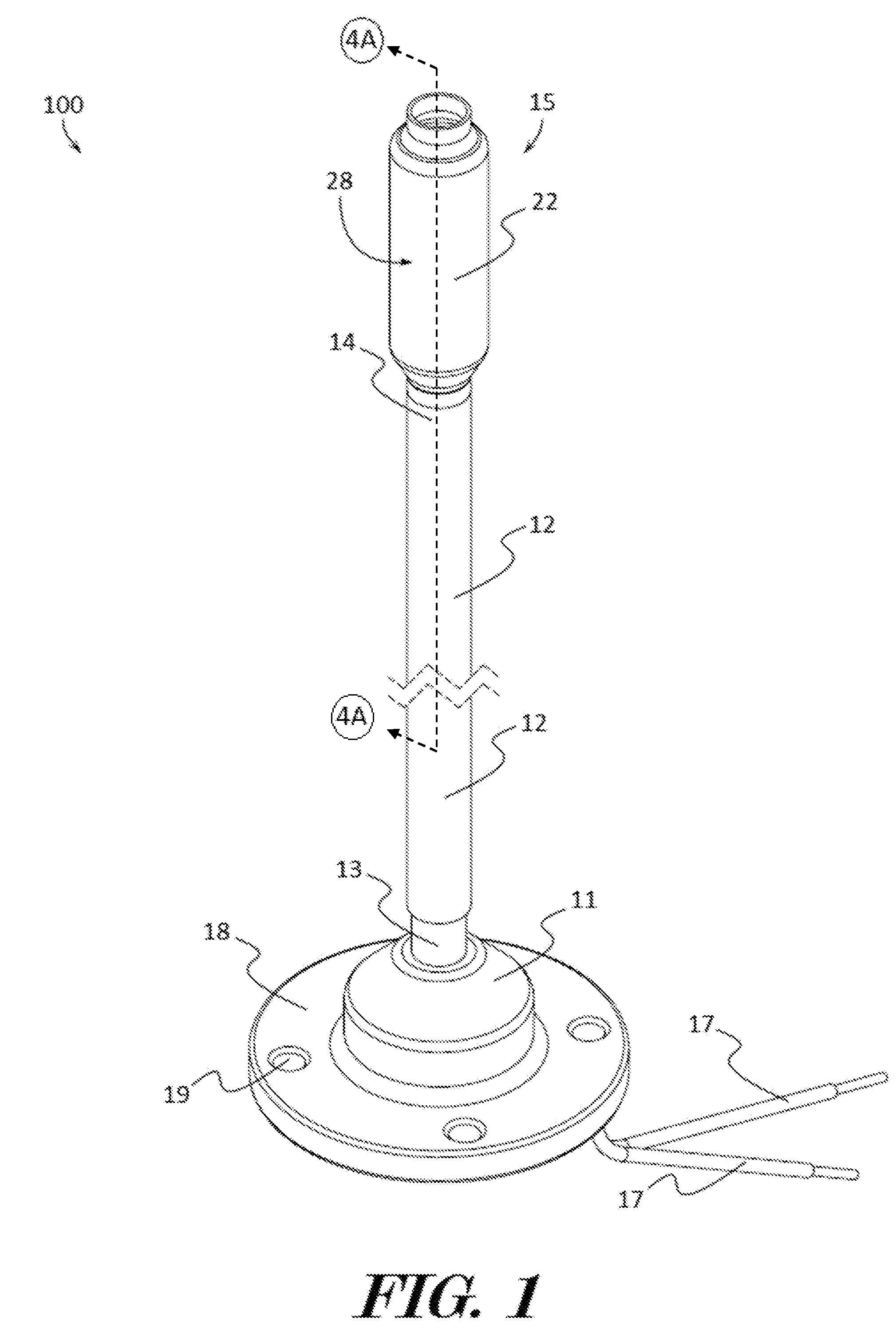
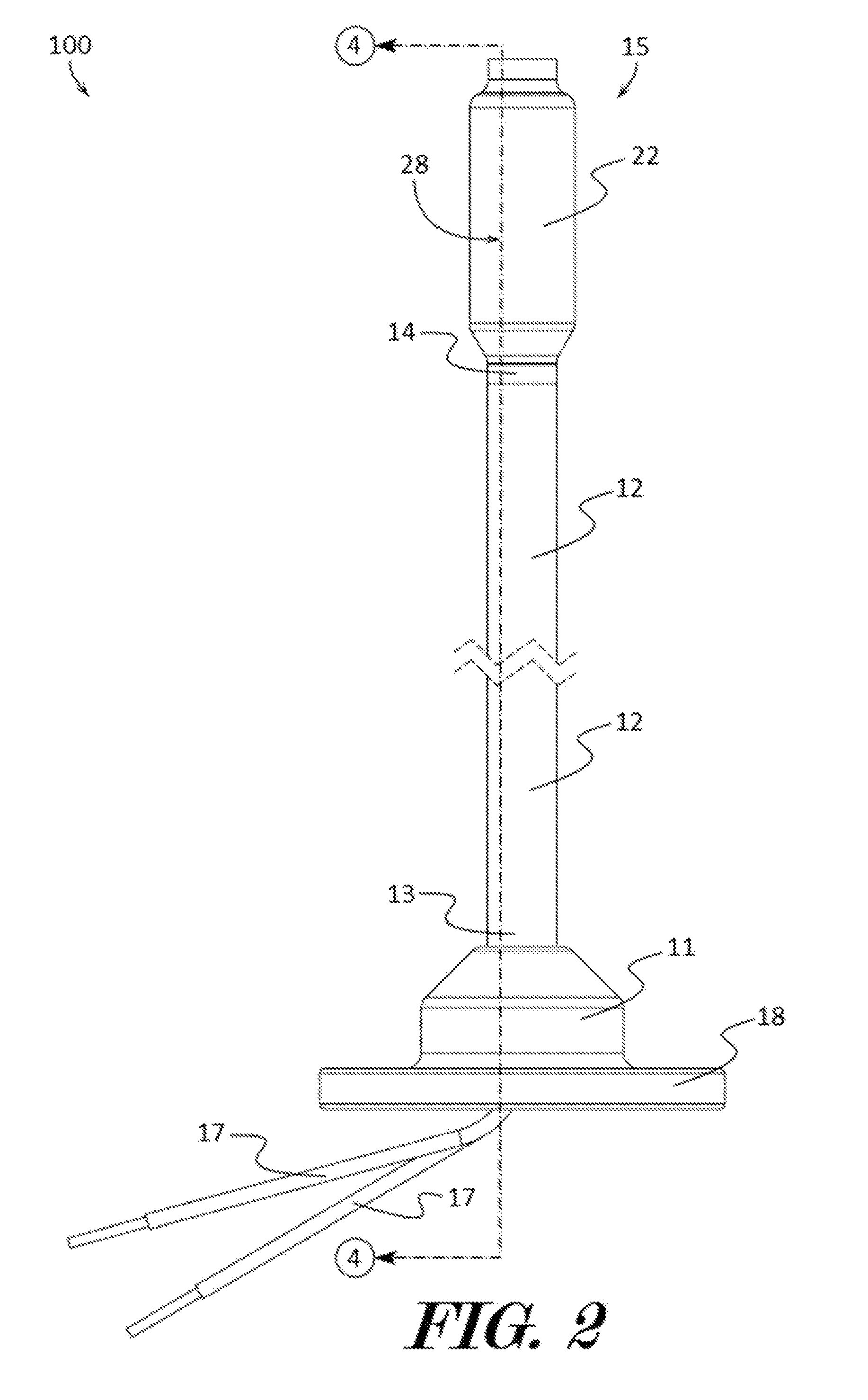
The patent text describes a marine navigation light apparatus that includes a base, a pole element, and a light assembly. The method of manufacturing the apparatus involves coupling the pole element to the base, inserting electrical wiring into the pole element, and connecting the wiring to the light assembly. The light assembly is designed to bend or flex while maintaining electrical communication with the wiring and is coupled to the end of the pole element using tubular shaped heat activated shrink wrap. The technical effect of this invention is to provide a durable and flexible light assembly that can withstand impact and can be easily coupled to a pole element.

Problems solved by technology

Due to the raised nature of the pole light positioned on the hull of the stern, this pole light is subject to frequent impacts and insults which often result in damage or breakage of the pole light.
While broken pole lights are time consuming and costly to fix, failure to maintain an operable pole light while operating a boat at night can result in dangerous conditions and even fines by waterway authorities.
However, upon reattaching the pole light to the hull, the pole light is once again subject to frequent impacts and insults which often result in damage or breakage of the pole light.
Due to the flexible nature of the pole, these flexible pole lights suffer from reduced strength and are even more prone to damage as they lose or gain flexibility due to exposure to the elements over time.

Method used


Image

  • Marine navigation light apparatuses and methods of making the same
  • Marine navigation light apparatuses and methods of making the same
  • Marine navigation light apparatuses and methods of making the same

Examples


Embodiment Construction

[0021]The terminology used herein is for the purpose of describing particular embodiments only and is not intended to be limiting of the invention. As used herein, the term “and / or” includes any and all combinations of one or more of the associated listed items. As used herein, the singular forms “a,”“an,” and “the” are intended to include the plural forms as well as the singular forms, unless the context clearly indicates otherwise. It will be further understood that the terms “comprises” and / or “comprising,” when used in this specification, specify the presence of stated features, steps, operations, elements, and / or components, but do not preclude the presence or addition of one or more other features, steps, operations, elements, components, and / or groups thereof.

[0022]Unless otherwise defined, all terms (including technical and scientific terms) used herein have the same meaning as commonly understood by one having ordinary skill in the art to which this invention belongs. It wi...


PUM

PropertyMeasurementUnit
transparentaaaaaaaaaa
impact resistantaaaaaaaaaa
flexibleaaaaaaaaaa

Abstract

A maritime navigation light apparatus comprising a pole element, a base, and a light assembly with one or more light emitting elements is presented. The pole element may comprise a hollow core and may be permanently or temporarily coupled to the base and / or to the light assembly. The light emitting elements may be housed on a circuit board and encased in an impact resistant encasement and electrically connected to electrical wires. The electrical wires may be inserted through the hollow core or the pole element and may also comprise electrical plug members which may terminate on the exterior or interior of the apparatus.

Description

CROSS REFERENCE TO RELATED APPLICATIONS[0001]This application claims priority to and the benefit of the filing date of U.S. Provisional Application No. 61 / 973,449, filed on Apr. 1, 2014, entitled “MARINE NAVIGATION AND ANCHOR POLE LIGHT APPARATUSES AND METHODS OF MAKING THE SAME”, which is hereby incorporated by reference in its entirety.FIELD OF THE INVENTION[0002]The present invention relates to the field of mechanical electrical interfaces in general. More specifically, the invention relates to electrical lighting interfaces for boats and other types of watercraft.BACKGROUND[0003]The use of lights in boats is a necessary requirement when operating a watercraft at night or in low visibility conditions. While the boat is operating on the water, the lights convey the orientation and position of the boat in the water to other watercraft. These lights are commonly known as “running lights” and typically comprise a red light and green light positioned along the bow of the boat and a wh...

Claims


Application Information

Patent Timeline
Patent Type & Authority Patents(United States)
IPC IPC(8): B60Q1/00F21V1/00F21V31/00B63B45/04
CPCB63B45/04F21V31/005Y10T29/49162
Inventor DEVEN, RANDAL A.SCHWEISS, JUSTIN E.
Owner DEVEN RANDAL A
Learn More