Magnetic sensor

a technology of magnetic sensor and magnetic field, applied in the field of magnetic sensor, can solve the problems of narrow installation choice range, large size of magnetic sensor in plan view, and inability to achieve small-size magnetic sensor, so as to achieve the effect of reducing the sensitivity of the magnetoresistive elements to the horizontal magnetic field components, improving the sensitivity to the vertical magnetic field components, and improving the sensitivity

Active Publication Date: 2016-12-27
ALPS ALPINE CO LTD
View PDF15 Cites 17 Cited by
  • Summary
  • Abstract
  • Description
  • Claims
  • Application Information

AI Technical Summary

Benefits of technology

[0016]According to the aspect of the present invention, by using a simple configuration, a magnetic sensor that employs magnetoresistive elements and that is capable of detecting a vertical magnetic field component can be manufactured. In addition, the magnetic sensor can be manufactured at a low cost, and a small-size magnetic sensor can be also achieved.
[0025]It is preferable that the magnetoresistive elements be formed on the substrate, an insulating layer be formed from the top of the magnetoresistive elements onto the substrate, and the soft magnetic body be formed on the insulating layer. Consequently, the magnetoresistive elements and the soft magnetic body can be easily and properly formed. In addition, the magnetoresistive elements can be properly arranged near an end portion of the undersurface of the soft magnetic body, and the horizontally converted magnetic field component can be properly supplied to the magnetoresistive elements from the soft magnetic body.

Problems solved by technology

However, a magnetic sensor employing Hall elements has a disadvantage that since the magnetic sensor uses ferrite chips, ferrite substrates, and a magnetic body as described in the patent documents, the magnetic sensor has a complicated configuration and uses a large number of parts.
Another disadvantage is that the magnetic body which connects the ferrite chips to each other extends a long way in the horizontal direction, so that the size of the magnetic sensor in plan view is larger than that of a typical magnetic sensor and a small-size magnetic sensor may not be achieved.
In addition, the Hall elements are required to be disposed separately from each other at both end positions of the magnetic body, causing another disadvantage that a range of choices for installation is narrow, in addition to the above-described disadvantage that a small-size magnetic sensor may not be achieved.
Thus, a configuration of a magnetic sensor that detects vertical and horizontal magnetic field components by employing Hall elements fails to improve the production efficiency effectively.
Instead of the magnetic sensor employing Hall elements as described above, a magnetic sensor employing magnetoresistive elements (MR elements) that exert a magnetoresistance effect (MR effect) is capable of detecting a horizontal magnetic field component that is parallel to a substrate surface, but is not capable of detecting a magnetic field component in the vertical direction with respect to the substrate surface.
However, a magnetic sensor employing any of the above-described configurations has a disadvantage that this magnetic sensor may not be manufactured at a low cost, and that non-uniformity of the products is likely to occur and a stable characteristic of magnetic detection fails to be obtained.

Method used


Image

  • Magnetic sensor
  • Magnetic sensor
  • Magnetic sensor

Examples


Embodiment Construction

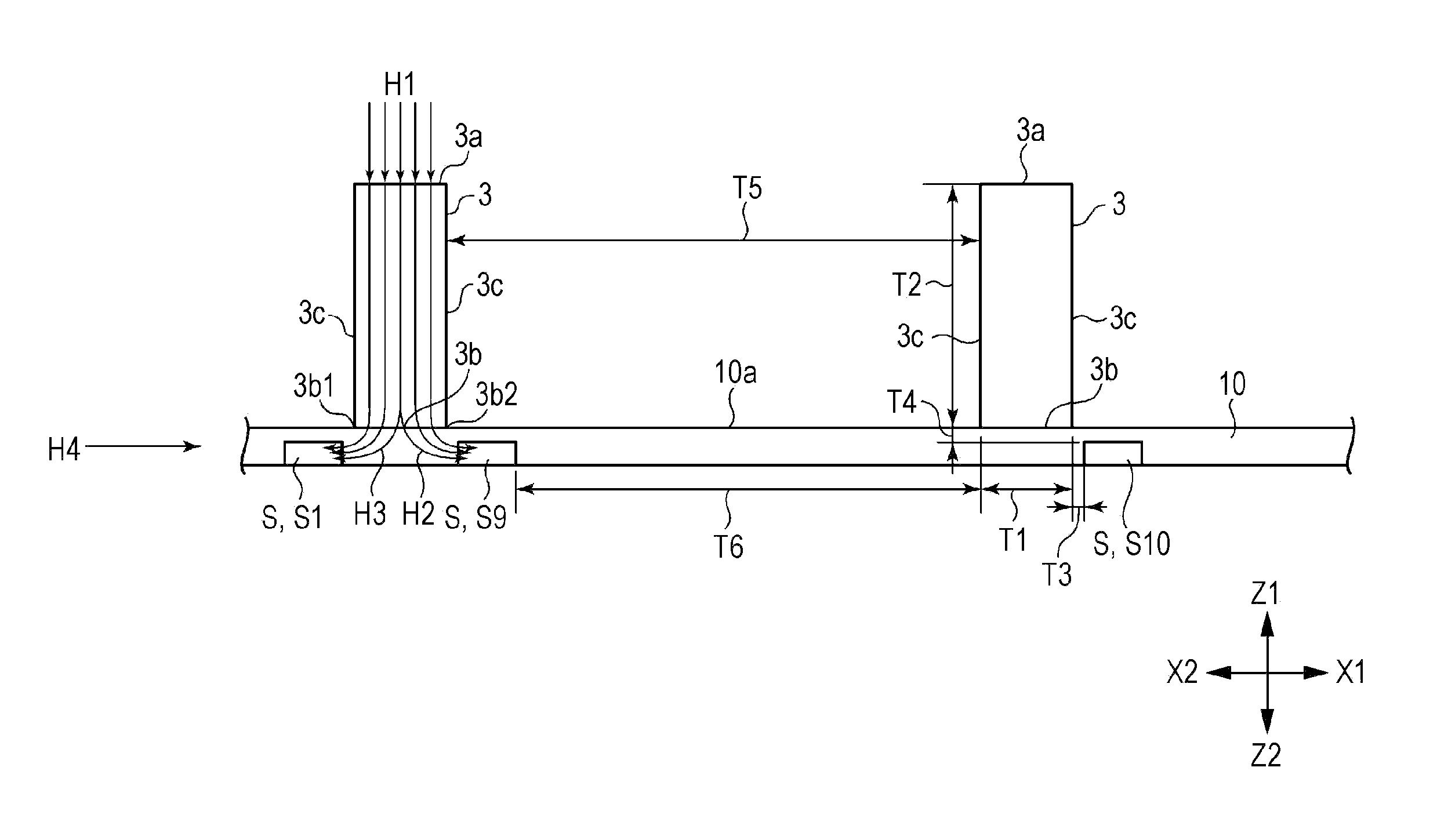
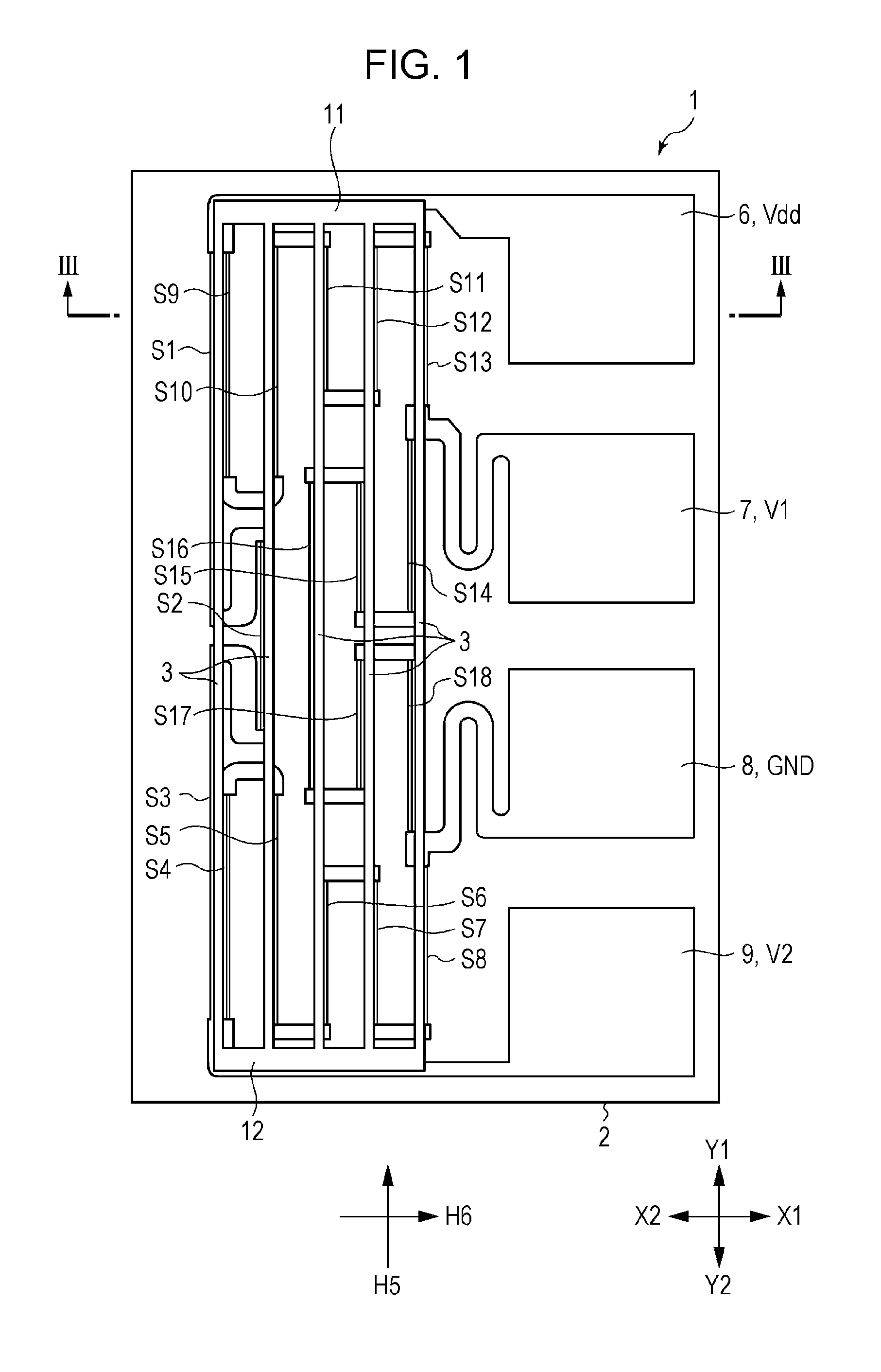
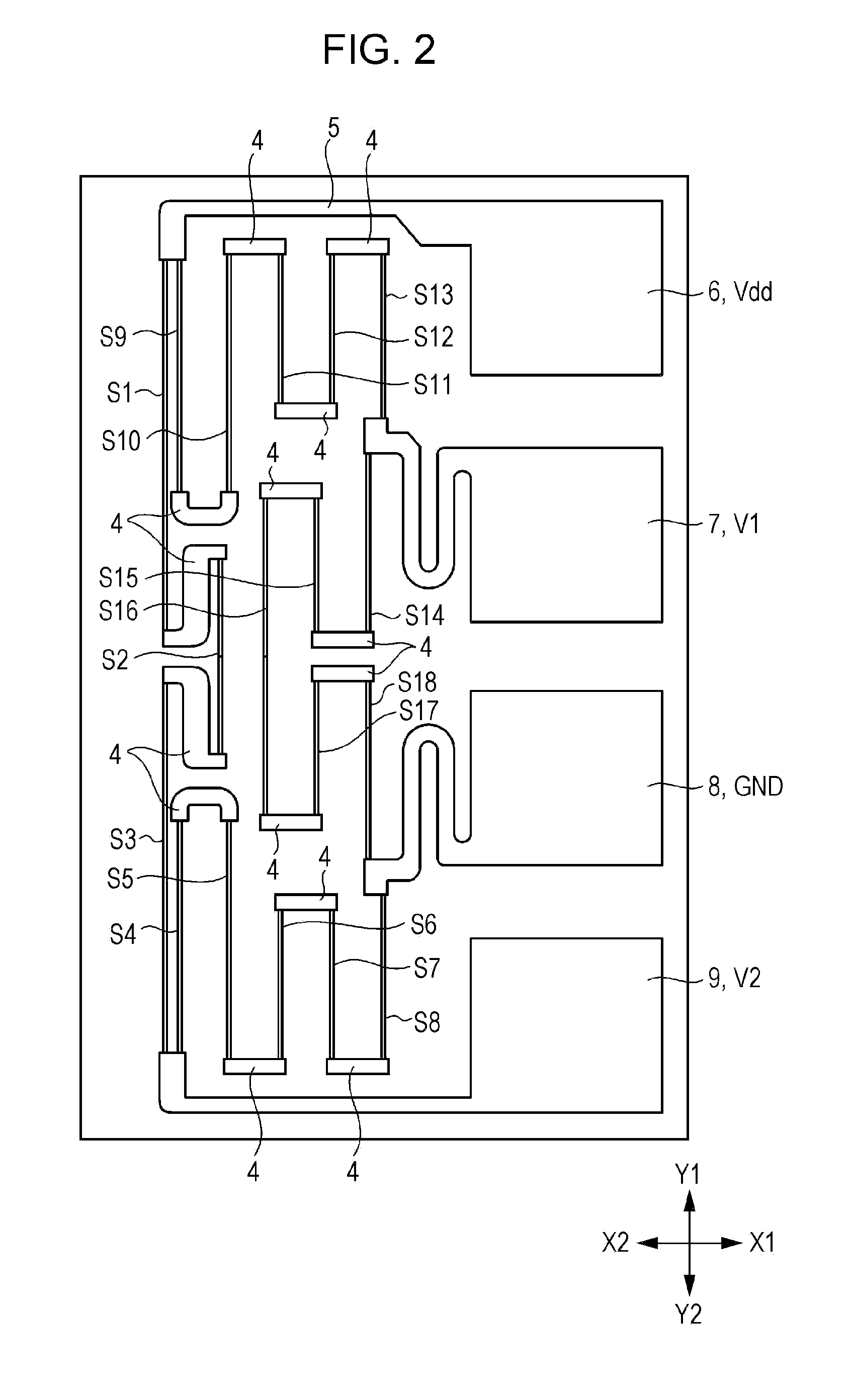
[0038]FIG. 1 is a plan view of a Z-axis magnetic sensor according to an embodiment of the present invention. FIG. 2 is a plan view of the Z-axis magnetic sensor illustrated in FIG. 1, from which first soft magnetic bodies and second soft magnetic bodies are removed. FIG. 3 is an enlarged partial vertical sectional view of the Z-axis magnetic sensor, taken along line III-III in the height direction and viewed in the direction of the arrows in FIG. 1. FIG. 4 is a circuit diagram of the Z-axis magnetic sensor according to the embodiment of the present invention. FIG. 5 is a partial vertical sectional view of a magnetoresistive element according to the embodiment of the present invention. FIGS. 6A and 6B are schematic diagrams (plan views) illustrating geomagnetic sensors each including a Z-axis magnetic sensor, an X-axis magnetic sensor, and a Y-axis magnetic sensor. FIG. 7 is a diagram illustrating strength of a magnetic field emitted from a soft magnetic body according to the embodim...


PUM


Abstract

A magnetic sensor includes magnetoresistive elements and a soft magnetic body. The magnetoresistive elements have multi layers including a magnetic layer and a nonmagnetic layer on a substrate, and exert a magnetoresistance effect. The soft magnetic body is electrically disconnected with the magnetoresistive elements, and converts a vertical magnetic field component from the outside into a magnetic field component in a horizontal direction so as to provide the magnetoresistive elements with the horizontally converted magnetic field component. The magnetoresistive elements have a pinned magnetic layer having a fixed magnetization direction and a free magnetic layer having a variable magnetization direction. The free magnetic layer is stacked on the pinned magnetic layer with a nonmagnetic layer interposed between the free magnetic layer and the pinned magnetic layer. The magnetization directions of the pinned magnetic layers of the magnetoresistive elements are the same direction. The magnetoresistive elements form a bridge circuit.

Description

CLAIM OF PRIORITY[0001]This application is a Continuation of International Application No. PCT / JP2010 / 071546 filed on Dec. 2, 2010, which claims benefit of Japanese Patent Application No. 2009-274131 filed on Dec. 2, 2009. The entire contents of each application noted above are hereby incorporated by reference.BACKGROUND OF THE INVENTION[0002]1. Field of the Invention[0003]The present invention relates to a magnetic sensor that employs magnetoresistive elements and that is capable of detecting a vertical magnetic field component.[0004]2. Description of the Related Art[0005]Magnetic sensors employing magnetoresistive elements may be used as, for example, a geomagnetic sensor that detects the earth's magnetic field and is incorporated into a portable device such as a mobile phone.[0006]A geomagnetic sensor is configured to detect each of magnetic field components in the X-axis direction and the Y-axis direction, which are orthogonal to each other in a horizontal plane, and the vertica...

Claims


Application Information

Patent Timeline
Patent Type & Authority Patents(United States)
IPC IPC(8): G01R33/09B82Y25/00G01R33/02H01L43/08
CPCH01L43/08B82Y25/00G01R33/0206G01R33/093H10N50/10
Inventor SUGIHARA, SHINJIKOIKE, FUMIHITOWATANABE, YASUSHIANDO, HIDETO
Owner ALPS ALPINE CO LTD
Why Eureka
Try Eureka